Failures and failure analysis
Several factors contribute to the complexity of structural claims. Complex structural claims typically involve a partial or a total collapse. Often, it’s not easy to determine the cause of the failure. Identifying the root cause of structural collapses requires expert analysis beyond a simple visual inspection of the structure.
Therefore, it’s no surprise that multiple parties would be interested, and the different parties will try to deflect the blame. However, various factors often contribute to structural failure or extensive damage. In addition, it’s not unusual to see that those factors reveal a latent defect that was at the heart of the collapse.
What to look for in a complex claim
Building safety and security is paramount in all claims, including complex ones. Therefore, a structural engineer should be retained from the beginning to assess the site and give instructions on safety measures.
Obligations under orders to remedy unsafe buildings – When there is severe damage, the city usually issues an order to fix a dangerous condition. Under that order, there is an obligation to retain a structural engineer to assess the site and give safety instructions.
Preexisting conditions’ impact or role is widespread in large losses. Preexisting conditions can cause structural deterioration and poor detailing, amongst other failure modes.
Mandatory code upgrades – When severe damage requires significant repairs or reconstruction, it must be upgraded to the current code. Otherwise, it will be unsafe.
Additional building permit requirements – These are needed if the footprint of the building is changed. Different permits will be required for different types of buildings.
Small changes that may lead to complex approvals – A footprint change requires approval. If the services are replaced, like a track or septic system, you need to get approval from the relevant governing bodies.
Document management in complex structural loss
- Collect documents early
- Be thorough
The documents in a complex structural loss differ from documents in other claims. There are numerous documents in construction matters. Therefore, it is crucial to collect documents early and be thorough. There’s no better opportunity to collect documents than at the beginning of a claim. As things progress, documents are likely to get lost or destroyed.
The primary documents to review in an ongoing construction include:
- Copies of the policies
- Contracts
- Subcontracts
- Payment certificates and invoices
- Drawings and specifications, including as-built drawings.
Drawings will help you determine if the construction is built to specifications. Contracts can be vital in apportioning liability and determining any relevant indemnities. So, ensure that you get copies of contracts between all the involved parties. Payment certificates and invoices related to the project are not always relevant in complex structural claims, but it is easier to get them at the beginning than at the end.
Even in projects without ongoing construction, you need to gather all the necessary documentation. These documents will help you establish liability.
The primary documents you will need are:
- Any original drawings or building permits
- Business interruption claim
Case Study 1: Masonry building collapse
A 100-year-old masonry building collapsed. Allegedly, one of the occupants on the second floor of this two-story building argued with one of his associates. The argument escalated, and the person came back to set the building on fire. The fire left the building badly damaged, and a restoration contractor was retained. As usual, the contractor gutted out the building for restoration.
The contractor found that the anterior leaf of the exterior walls was cracked, bolted out, and appears to have sustained water damage. The contractor brought this to the attention of the engineer retained to assist with the restoration of the building. As a result, they decided to address this damage as part of the overall scope of repair for the installation.
Around the same time, there was road construction on the street near the exterior wall. Part of the road construction was to replace the concrete sidewalks along the length of the wall. The construction caused the outer leaf to collapse partially, and the building was condemned and reconstructed.

Figure 1: The initial wall collapse in the outer leaf (left) and the final wall collapse (right)
Initial observations
The outer leaf damage covered a 34ft x 40ft area. You could see a hole indicating that the even part of the anterior leaf of the wall had collapsed. The day after the initial collapse, that entire wall section collapsed, including the exterior and interior leaves (figure 1). It was a load-bearing wall, so the failure impacted the floor and roof support and the adjacent walls. The building was unsafe and in imminent danger of complete collapse. As such, it was better to have controlled demolition instead of waiting for the building to collapse on its own.

Figure 2: Failure mechanism of the wall
The left-hand side image in figure 2 illustrates the masonry wall. The masonry wall was supported on a Rubble foundation wall. The circled part represents the floor level, and the left-hand side shows the sidewalk. As indicated, the masonry wall was a double-leaf wall, and those two leaves were connected by header units that went across to tie the two leaves together.
In the construction before the incident, it appears that at least part of the outer leaf was bearing directly on the concrete sidewalk. When the contractor removed that part of the sidewalk, the nearby portion of the wall collapsed. When the wall in the original construction is intact, you have total load-bearing capacity.
Over time, those ties between the two leaves crack and separate. So, instead of having one thick masonry wall, you have a wall that consists of two layers acting separately. The impact of that is a reduction by about 50% in load-bearing capacity. However, that would still not be enough to cause building collapse.
The 50% reduction of the wall capacity exhausted all the built-in safety factors in this design. The right-hand side illustration in figure 2 shows the wall already separated into two separate leaves. In addition, the inner leaf had been cracked and bolted in after the removal of finishes because of the fire, so it had already deteriorated.
Preliminary findings and analysis
Our structural analysis showed that the remaining capacity of the wall was down to only 15% of its total capacity when it had initially been intact. It was, therefore, no surprise that the wall fell. While several other factors could have contributed to the building collapse, it’s essential to acknowledge that the building was old, with deterioration to parts of the masonry walls. In addition, the cracks on this wall were up to 3 mm wide, and the two leaves had already separated.
Conclusion
Our analysis showed that even without the fire, the main exterior wall would have collapsed due to the removal of the concrete sidewalk. Removal of this central load-bearing external wall compromised the structural integrity of the entire building. Hence, the building needed to be demolished and reconstructed.
Case study 2: The mystery of wind uplift to a farm building
In the 1970s, a farm building in Saskatchewan reportedly sustained wind damage for the third time in five years. Unfortunately, the insurance company had three inspectors and engineers before us, and they could not find the cause of the uplift and damage to the farm building.

Figure 3: The Approx. 50-year-old single-storey farm building (left) and its interior (right)
Initial observations
The property was a single-story building covered with a gable roof and exterior finishes. The finishes had sheet metal cladding on the walls and ceiling. In addition, 16-feet high walls enclosed the farm.
The gable roof (figure 3, right) was framed with 25 metal plate-connected wood trusses spaced 4-feet apart, which is typical. The trusses were tied with purlins spaced two feet apart. The walls were framed with pressure-treated wood posts affixed to the exterior walls. Plywood panels were installed inside the building at the bottom of the exterior walls. So, the pressure-treated posts were embedded in the ground and served as the building’s foundation.
Two pressure-treated timbers were secured to the posts at the ground level and all around the building to serve as a standoff below the metal cladding.
The farm building had a 24-feet wide sliding door on the north wall (figure 4). At the time of our examination, the sliding door was not functioning correctly. A two-inch wide gap was observed at the top between the door panels and the broader clearance near the corner between the sliding door and the bottom track.

Figure 4: The dysfunctional sliding door
As indicated in figure 5, we observed a slight uplift and bowing in the roof and wall. They were on the opposite sides of the farm building.

Figure 5: The uplift and bowing observed in the building.
There was also a slight uplift in the post and the surrounding soil near one of the walls. In addition, the plywood in the interior wall had an upward slope of nearly one degree. That was an indication that this end of the wall had been uplifted.

Figure 6: The building drawing we developed (left) and the vacuum excavation performed on timber columns to remove “problematic soil” (right).
The uplift on the front side of the building seemed to have been an ongoing issue. The elevation view of the farm building in figure 6 shows the dimensions of the building components, including the half-inch thick plywood sheet installed after the first uplift incident. The previous engineers and contractors thought that could help alleviate the issue of lifting around the corner.
They performed hydrovac (vacuum excavation) on all timber posts to remove the problematic soil and replace it with one-inch tamper gravel around the root post. Vacuum excavation is a non-destructive digging process and a method of suction excavation that consists of injecting pressurized water in a vacuum system to dig out the soil. However, even after these two processes, the issue persisted.
Preliminary findings and analysis

Figure 7: Review of historical climate data
To clearly understand the cause of this problem, we examined the wind gust. Since the building was almost 50 years old, the 1965 or 1970 edition of the Canadian Code for Foreign Buildings would have been in effect at the time of construction. Both editions refer to the National Building Code of Canada (NBCC) for wind design values.
As shown in figure 7, wind design data for the province of Saskatchewan was the same in both the 1965 and 1970 editions of NBCC. Therefore, if the subject farm building had been engineered, it would have been designed to withstand a wind gust of 141 km/h. This is based on the 1965/1970 MVC design data for the closest city to the subject property.
Based on the climate change and Environment Canada data, the maximum wind gusts recorded at the nearest location was 89 km/h. The graph in figure 7 shows months in 2020 for four different areas close to the subject property. The maximum wind gust was 89 km/h in May, significantly lower than the design code.
Preliminary findings and analysis: the building construction

Figure 8: In-depth analysis of the construction.
Since the wind gust was not above the design, we took a closer look at the building construction. Figure 8 shows two diagonal braces on the north wall of the sliding door and one brace on the west end of the south wall.
In addition to resisting gravitational loads, a structure must be appropriately framed and designed to withstand lateral loads that would be impacted by wind pressure. The farm buildings did not have adequate framing to resist lateral loads. Only the single continuous bracing was observed on the north wall, as shown on the left-hand side images in figure 8.
Conclusion

Figure 9: The plan view of the building.
We looked closer at the plan view of the drawings to understand its framing and structure. The north and south end walls were the only parts that resisted the wind blowing in the east-west direction.
The opening on the 24-feet wide sliding door reduced the stiffness of the north wall by approximately 50% compared to the south one. The imbalance resulted in the development of twisting of the building under wind pressure. The twist lifted the post on the north wall, east of the sliding door – the location that had problems.
The imbalance between the center of mass and the center of rigidity caused the twisting of the building. The center of mass is the point where the entire mass of the floor acts, and the center of rigidity is where the entire stiffness of the building acts. Therefore, the more distance between these two points, the more twisting a building will experience.
We could not find evidence that the farm building was engineered correctly, and the wind pressure never exceeded the building design code of 141 km/h.
We concluded that significant preexisting structural deficiencies rendered the building vulnerable to twisting and uplifting under the wind. The building lacked adequate lateral load resisting systems and wide-spaced roof trusses. Wood posts are typically supported on concrete piers that extend about four feet below grade. The posts of the farm building were six feet deep in the ground without any bearings, which is analogous to sticking needles in the ground.
Replacing the soil around the post of the farm building with gravel using hydrovac most likely weakened the resistance of the embedded posts to uplift because gravel has a lower friction capacity than clay or silt.
Case Study 3: Sand bins collapse
Frac sand refers to the hydraulic fracturing process. The process requires a specific grain size and quality of sand. An industrial facility that sold frac sand to the oil and gas industry experienced a collapse of sand bins. They were expanding their facility, and they added four bins.

Figure 10: A bird’s eye view of half the structure (left) and the consignment side view (right).
The consignment (figure 10, left) had a steel frame to elevate the bins. The cone hopper allowed trucks to receive a load of sand from beneath.
The top view also shows the columns and beams that elevate the bins; each bin sits on its ring frame. The four points indicate the load cells where the green lines meet the red-ish parallel lines. They keep track of the weight of each bin to monitor how much sand goes in or out. These bins each had a nominal capacity of 160 tonnes, a substantial amount of sand.
The structure had been recently constructed, and the incident details are shown in figure 11:

Figure 11: The incident details
Bin #4 was removed to make the site safer for investigation because it presented a hazard.
Initial observations
We observed several potential causes of the collapse, including manufacturing, design, and installation deficiencies. Bins #2 and #3, which collapsed first, were the middle bins. The red-ish girder supported all four bins, and five columns reinforced each beam.
We analyzed the entire structure and didn’t indicate a problem with the columns or the beam sizes. So we quickly ruled out the foundation, bin, and load cell.
Preliminary findings and analysis
After ruling out the beams and columns, we focused on the connections between those parts. When we started focusing on the connections, we identified a critical link at the middle column line, as shown below:

Figure 12: The critical connection, indicated by red circles.
This was designed to be one continuous girder across five columns. But that was changed so that two girders joined over the column.

Figure 13: Critical connection detail.
Figure 13 shows the top view of the girder continuous over the column. The column had a cat plate. The side view on the right-hand side shows the I-beam and the wide flange beam. Beneath the beams are the flanges of the column. The column was intended to be continuous, but it was changed to a design where the end of the beam was sitting on the plate itself.

Figure 14: The noncontinuous column connection.
During our analysis, we identified that the plate was significantly under-designed. It was substantially deformed. We analyzed it using a yield line analysis and estimated the failure load to cause this type of failure would be about 62,000 pounds. But this alone would not have brought the structure down.
Once it starts to yield, the plate behaves like a stretched sheet. So, it would still have the reserved capacity, as long as nothing else went wrong. This might have bought enough time for someone to see it in an inspection. But that’s not what happened because there was another problem.
Conclusion
Since the beam was not continuous, its end was more vulnerable to web crippling. And that’s what we see in the image in figure 15:

Figure 15: A split beam with web crippling.
The web slightly folded in on itself from the stresses at the end of the beam. We predicted a failure mode of about 80,000 pounds, which was close to the estimated load at the failure. As the plate started to yield, it reduced the effective support line on which this beam was sitting. And then, the web crippling occurred.
The final straw was the bolts that held everything together, snapping and tearing out. So, this collapse of the sand bin structure came down to a single connection that was conceptually changed without follow through. In addition, the connection was not checked to ensure the load path was still acceptable.
The column cap plates began to yield, which reduced the effective support length for the beams. Then, beam web crippling occurred. Finally, the bolts holding the beams onto the columns failed, resulting in bins #2 and #3 collapsing. The extensive amount of damage to the structure in the process of collapsing resulted in bin #1 also collapsing.
Case Study 4: The sudden collapse of a church’s gable roof
A single-story Church, which was over 100 years old, had a gable roof collapse under heavy snow. The roof ridge was along the north-south direction. The whole building was a wood-framed construction, and the south of the building was extended in the 1960s.

Figure 16: The general view of the building.
The unsafe conditions of the building made this a complex claim. First, we could not get inside the building or around it to see the connections. The other factor was the nature of the incident – the sudden roof collapse of a public building.
Public buildings have stringent design requirements. We usually see a roof collapse in buildings that have relaxed design requirements. The failure mechanism of the church building was rare, which added to the complexity of the case.
Initial observations
The collapse was only concentrated on the roof of the extended building. The roof of the original building was almost intact. However, it was unsafe to enter, so we relied on drone-assisted inspection to visualize the interior of the standing roof.
We investigated the design ground snow load based on the code at the time the extension was built, which was NBC 1960. The roof should have been designed for a 33-inch ground snow load based on the code. We further looked at historical weather data and found that the ground snow load was 21 inches on the date of the failure, and the maximum historical ground snow load for the location of the building was 53 inches.
Had the building been designed to the code of the time, it would have easily carried the snow on the date of loss. So, we hypothesized that there must be something wrong with the structure.

Figure 17: A section of the gable roof (left) and a typical Rafter-ceiling joist connection.
The rafters carry the gravity loads indicated by the blue arrows coming vertically down. As a result, they produce compressive forces in the rafters. These compressive forces have horizontal and vertical forces.
The corner takes the vertical force. So, you will have compression in the columns. On the other hand, the ceiling joists make the horizontal force, so you have tension in the ceiling joists. This means the rafters must be appropriately connected to the ceiling joist. Otherwise, the edge will slide out and under, making the roof cave in. The right-hand side image in figure 17 illustrates the detail of a typical construction at the edge of the roof.

Figure 18: The general structure of the failed roof.
The rafter was sitting on a plate fastened to a rim board. In the photo, you can see the ceiling joist and the rafters. The rafters were sitting on a top plate, and the rim board was connected to the ceiling joist. The tension in the ceiling joist means the nails shown on the left-side in figure 18 were in tension. The nails have a smooth shank, and they were embedded at the end of the ceiling joist. So, they are fragile in carrying tension, and they could easily withdraw from the end of the ceiling joists.
Preliminary findings and analysis

Figure 19:Construction detail of the subject building (left) and a typical rafter-to-ceiling joist connection (right).
In the configuration above (right), the shanks of the nails are not in tension; they are in shear. This is not a sudden failure mechanism; it is gradual.

Figure 20: Source – Google Maps
We took this image from Google Maps. It was taken a couple of years before the date of loss. The roof part that’s not circled is the original building where the roof is sound. There’s significant visible sagging on the extended side of the building.
Conclusion
The probable cause of the collapse was preexisting construction deficiency. The construction deficiency was the improper connection of rafters to the ceiling joists. However, our analysis showed that this was not the actual cause.
We concluded that the collapse resulted from a gradual failure of connections over many years. The depth of roof snow on the date of loss was less than the design snow load. If it had been designed properly, it would not have collapsed. Contrary to initial assumptions, the presence of snow on top of the roof does not necessarily mean it will cause the roof to collapse.
Complex structural claims: Legal case studies
Case Study 1: Cracking foundation
Foundation damage was found in a heritage building. There was adjacent high-rise construction, and damage was noticed during the excavation and shoring of that construction. And so, the high-rise contractor was put on notice.

Figure 21: The damaged east wall of the heritage building.
Figure 21 shows the excavation and shoring that the contractors performed to the east. Again, it’s important to note that the shoring work is flat and uniform across the surface.
Initial observations
We noticed that some wood lagging was installed in the excavated area during the investigation. However, there was no apparent reason for this lagging. There was interior damage to the foundation of the heritage building on the other side of that lagging. Therefore, we considered the lagging a potential source of the foundation damage to the building.
The damage included a 3′ by 8′ section of the east foundation wall bulging into the occupied space. Cracking was later found in the east exterior wall at the roof interface vertically in line with the section of the damaged foundation. The excavation on the east side of the building was assumed to be the cause.

Figure 22: The East excavation and wood lagging that was installed.
We hypothesized that the damage likely occurred during the excavation and scraping of the east wall by the excavator bucket. This is because that’s how the uniform surface was achieved. However, an engineering inspection determined that the cracking and bulging were preexisting. Therefore, we had to determine the extent of the preexisting damage compared to the damage caused by the adjacent construction.
The three insurance policies were in place during the incident. There was a builder’s risk policy that refused coverage. They typically apply to only property under construction. The CGL and Wrap-up liability insurers also denied involvement because the damage was not caused by apparent negligence.
The expert opinion determined that the damage was preexisting and naturally occurring, given the age of the building. On the other hand, there was an apparent construction disturbance to the east, along with the complaints by the occupants.
Preliminary findings and analysis
The ongoing monitoring by the engineer revealed further cracking in the building. The additional cracking was occurring at a rate greater than natural deterioration. The accelerated pace of the cracking could only be related to the construction vibrations. So, the ongoing damage to the heritage building exposed the liability insurers. We had to determine whether the contractors were negligent. Preexisting cracking did not necessarily mean that the contractors breached the standard of care.
The heritage building owner secured a Tieback and Crane Swing Agreement with the general contractor before construction commenced. The tieback agreement contained an indemnity clause favorable to the heritage building owner. The agreement also included a clause ensuring that the general contractor secured insurance coverage for liability assumed in the contract. The tieback agreement exposed the liability insurers as a result.
Resolution
The policies had the insured contract exceptions to the typical exclusion for liability assumed in the contract. In some cases, the certified agreements that exclude liability and contract exclusion are pretty limited. They’re sometimes listed as particular types of arrangements. And if you don’t fall into any one of those categories, you don’t fall into the exception. In other cases, it’s contracts that are usual to the insured’s business. In this case, the tieback agreement was familiar to this insurance business. And so, there was exposure.
The indemnity language in the agreement was significantly broad. For example, part of the indemnity stated: “The company agrees to indemnify and save the owner harmless from and against any claims incurred by the owner and arising directly or indirectly, out of, or about the exercise by the company have the rights granted to the company under the agreement.”
Generally looking at this type of wording, the case law will choose the broadest language and apply it. Whether you think “indirectly” is more expansive than “about” or vice versa, a court will make that determination, and they will apply the broadest language. It goes on to say, “And in connection with the construction and completion of the project.” So, whoever drafted the indemnity agreement tried to touch on all the different ways that there could be some connection to a liability.
It further says, “The company agrees to indemnify the owner in respect of all claims arising out of any damage caused to the lands and any buildings, the heritage building itself, arising directly or indirectly, from or incidental to.” This language is inclusive of all the parties.
The agreement further refers to “any negligence or omissions” by the company. The final paragraph brings the general contractor’s subcontractors into the fold, making the general contractor responsible for all of them as well. This was drafted to put all types of exposure onto the insurers. Given that the exclusion for liability assumed in the contract was either removed or fell within the exception of the insured contract, that goal seems to be achieved.
Lessons learned
Ongoing construction projects may include constant monitoring capable of altering initial engineering opinion. If that type of work continues, it’s essential to stay on top of those developments. You cannot close a file because of an initial engineering opinion; a detailed investigation provides more balanced findings. Therefore, it was essential to retain an engineer to vet the inspections and monitoring performed by the adjacent landowner’s engineer.
The tieback agreements need to be identified early, given the potential and significant unanticipated exposure, and if possible, before it is executed by the insured to appreciate the insurance risks before the work begins. That’s more difficult to do in the CGL context. You may not know what an insured is doing under the assumption that they’re covered under the CGL. But the wrap-up policies are generally issued on a project-by-project basis.
Case Study 2: A roof collapse
The sizeable sprawling roof of a residential home shifted under a load of snow, causing significant structural damage throughout the house. The homeowner’s insurer denied coverage and based that denial on the exclusion for faulty workmanship.

Figure 23: A photograph of the home.
As shown in figure 23, the roof was wide.
Initial observations
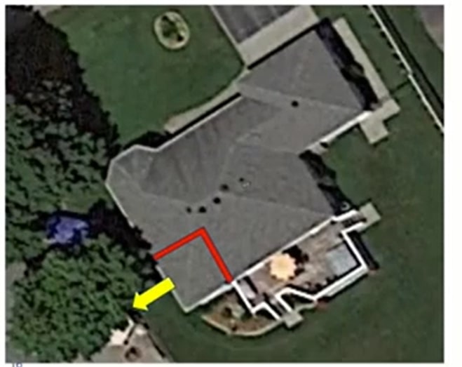
Figure 24: An aerial view of the home. Source – Google Maps
The red right angle in figure 24 shows the area of the damage. Underneath that marked area was the den, and it had a cathedral ceiling. In a typical room, two edges of the walls have ceiling joists running across the entire length of the room. To create the vaulted appearance of a cathedral ceiling, you have to remove the ceiling joists. In the absence of these joists, rafters must be adequately braced.

Figure 25: A picture of the framing of the home from 30 or 40 years ago.
The image above shows a wall separating the den and the kitchen. The red line marks the edge of the kitchen wall. At the top of the kitchen wall edge, there are 2′ by 6′ ceiling joists that are cut. The blue line represents the intention of the designer to extend those joists from the kitchen wall across the den to the exterior wall that ended up protruding and bowing outward under the snow load.
Had those joists been installed, they would have provided additional support for the exterior wall, pulling and securing it against the internal kitchen wall. It would have prevented the cathedral roof failure.
Preliminary findings and analysis
We were dealing with old construction from the 1990s, and its design records were not available. The town switched corporate identities over the years, and documents were lost. So there was no way to tell if the issue was related to design or quality.
This presented a problem because the plaintiff had the burden to prove a claim falls within coverage. And then the defendant insurer had the burden to prove the exclusion upon which it relied.
Preliminary findings and analysis: Case Law
In the case of Dawson Creek v. Zurich, the British Columbia Court of Appeal looked at very similar facts. The two cases had virtually identical facts. In the Dawson Creek v. Zurich case, an arena roof collapsed under snow load. The building was 40 years old, and there were no records of the original design.
The argument was that it must be a design or workmanship issue. If the builder fails to install the joists, it’s a quality issue. Suppose the joists were never supposed to be there by design. But the court didn’t accept that reason. So the insurer still had the onus to prove one of the exclusions. But the lack of records and facts made it impossible to prove any of the exclusions applied. So the insurer could not prove either exclusion.
There’s a similar case in 2008 from Ontario. In that case, the court said that Inherent Vice is challenging to define. Some courts have referred to it as deterioration of construction materials. So, you would need to have evidence of deterioration. But that wasn’t going to be likely on our set of facts because we’re dealing with a failed roof. So, we could not establish corruption.
In Dawson’s Creek v. Zurich, the Court of Appeal reasoned that you’d also have to prove that the defect was, in fact, latent. As part of this latent defect exclusion, you’d have to show that the fault was not discoverable upon inspection. They also said that it’s an exclusion that should be considered distinguishable from construction defects, excluded explicitly under the quality exclusion. The Court of Appeal went on to say that the Inherent Vice and Latent defect exclusion should generally apply more to perishable goods.
We knew we had to prove the faulty workmanship exclusion based on these two previous rulings. We acquired a copy of the blueprint for the home.

Figure 26: The blueprint of the home.
The yellow line on the blueprints represents the joists. It intends to connect that exterior wall to the wall that failed under the cathedral ceiling to provide additional support across the back end of the home.
To acquire the blueprint, we got a copy of the subdivision plan, after which we identified homes with similar models. Then, those homes were visited, and we found a blueprint identical to the design of the collapsed house.
Resolution
The blueprint helped us prove the quality issue because it clearly shows that the joist was supposed to be there and that the builder went against the design specifications. While this information was invaluable, the case wasn’t closed. We had to rely on the exclusion wording on the insurance policy. The Homeowner had an “all-risks” Homeowner’s policy, including specific collapse coverage.
Figure 27: The policy wording.
The Homeowner’s insurance policy had a resultant damage exception. As indicated in figure 27, the policy did not insure the cost of making good faulty workmanship unless physical damage not otherwise excluded by the policy resulted.
The plaintiff argued that their roof collapsed because lateral bracing between the rafters in the cathedral ceiling was not present, as shown in the exemplary photo below (figure 28):

Figure 28: The exemplary photo of the cathedral ceiling.
The dark wood rafters show that there are no ceiling joists. The plaintiff argued that a relatively inexpensive fix to the lateral bracing would have prevented the roof from collapsing. The insured’s position was that the engineering opinion lacked lateral bracing, allowing the rafters to shift in the same direction under a load of snow.
The same forces push the exterior walls outward, and the lack of lateral bracing could be remedied with inexpensive steel strapping. The point of this argument was that everything else was resultant damage. Additionally, we still needed to look further into the scope of the damages, and this is what we discovered:

Figure 29: A drawing showing the design and construction of the house.
The white line depicts the cathedral ceiling, and the orange line shows the joists that were supposed to be in place but were not. Upon further inspection of the damages to the roof, we noticed that the collar tie indicated by the blue was over-spinning. It was twice the length required by the building code.
The rafters that were supposed to be spaced out every few feet were spaced out twice the length of the building code requirement. We determined that the builder ultimately failed to install the roof to code or design. As a result, all rafters and collar ties had to be replaced. In addition, the joists had to be installed, and the cathedral ceiling had to be adequately braced.
Ultimately, the entire roof was excluded for faulty quality, while the main floor and basement were likely resultant damage.
Case Study 3: Concurrent coverage
A flood occurred at night, during off-hours. The resulting damage to a water line caused a leak. The water damage occurred while adding to a commercial building under construction. There was a Builder’s Risk insurance policy in place during construction. There was also First-Party property insurance in place for the existing building.
Waterline failure caused damage throughout the existing building. The concurrent coverage was the First-Party property for the system building and the Builder’s Risk (COC).

Figure 30: A photo of the waterline that failed.
Initial observations
In figure 30, you can see that the coupling engages a fair portion of the pipe that it’s attached to, leaving only a limited space for the other pipe to adhere. This could potentially be an installation issue. But on the other hand, there are odd cuts in the pipe, indicating a lack of care or a coupling issue.
The parties covered under the Builder’s Risk included the owner, general contractor, subcontractors, security staff, and suppliers. In addition, the owner is also covered under the First-Party property policy.
Preliminary findings and analysis
The failed water line was removed and stored for destructive testing. The representation at the testing was intended to include the anticipated insured individuals. The insurer’s investigators conducted interviews, including with the representatives of insured individuals.
Resolution
All those connected to the waterline were covered under the Builder’s Risk. Therefore, further investigation was determined unnecessary. As a result, destructive testing was never carried out, and the cause was never determined. However, a chain of custody and preservation of evidence issue arose nonetheless.
A cautionary note here is the lack of consideration for a potential manufacturing failure. The investigators did not consider a manufacturing warranty to respond to this loss. By removing the pipe and not ensuring a chain of custody. Even if there were some exposures on the manufacturer, there’s a potential for a limited liability clause in the warranty wording.
It is difficult to say whether this manufacturer would have ever been responsible and potentially unlikely, but it bears a cautionary note. The main issue that arose after this investigation was jurisdiction.
The two insurance companies did not know how to divide the loss. The debate over the jurisdiction cost delays and potentially caused prejudice to the insured. Those delays prevented the repair of the building from occurring promptly.
OCI Group: Leading Experts for Structural Claims
Our forensic experts have a lot of experience conducting investigations, writing reports, and testifying in court as expert witnesses. Call 1-888-624-3473 if you’re dealing with structural complex claims and property loss. We will conduct a comprehensive investigation based only on facts and evidence.
The investigation of losses typically requires the same methodology, therefore, we always use the methods outlined in the NFPA 921 Guide for Fire and Explosion Investigations. The methodology for fire investigations requires three steps, which have several mini-steps within themselves.
- Determining the origin of the fire – To do this, we use fire pattern analysis, consider witness information, and consider fire dynamics.
- Determining the cause – The cause could be related to equipment failure or product failure. It could also be related to human action or electrical failure.
- Finding circumstances for how the ignition source ignited the first fuel – This information may help you find potentially responsible parties. Moreover, it could help you determine the next steps for the insurance company.
Fire investigations often involve multiple parties. As such, it’s crucial to have more organization of the fire scene. As a result, there is more time to make the structure safe, and in the actual investigation, tough losses could take several days or weeks. There’s also a higher chance of working with public service agencies such as the Office of the Fire Marshal, local Fire Departments, the Ministry of Labor, and Police Departments. Sometimes our scenes may be spoiled by previous investigators, especially in cases with sizeable public exposure. We often find this in big cities and hazardous losses.
Complex fire loss standards
In large and complex losses, we must consider standards ASTM E1188 and ASTM E860, amongst others.
- ASTM E1188 – The standard practice for collecting and preserving information and physical items by a technical investigator.
- ASTM E860 – The standard practice for examining and preparing items that may become involved in criminal or civil litigation.
Both standards and the NFPA 921 are guides to preserving evidence, destructive or nondestructive testing, and evidence destruction. The standards set guidelines so that all parties interested in the loss have the same opportunity for evidence examination in its original condition and location. If any party does not follow these guidelines, another party may bring an action of evidence spoliation against the offending party. And with large and complex losses, there is a higher chance of procedures not being followed.
The nature of large and complex losses means there’s potentially more information available. This information could be from first witnesses, CCTV camera surveillance, the Fire Department, the Fire Commissioner, and other agencies. Even the Building Department and Fire Code Reviews may provide further information on why fire spreads rapidly.
There are more complex systems we need to evaluate during losses. These systems provide more information that may support other evidence. Therefore, all available information must be taken into perspective.
Case Study 1: Municipal building fire

Figure 1: A bystander supplied photo of the fire
A municipal building experienced a total fire loss which cost over $5 million. Fortunately, the Fire Chief was familiar with the structure and knew where the fire was first observed before it spread throughout the building. As a result, the fire was first kept above the garage area.
The complexity of this loss comes from the fact that the roof was insulated with cellulose insulation above the ceiling level and how the fire spread across the top. Cellulose insulation uses a recycled paper product treated with boric acid, a fire retardant. The cellulose insulation is blown into the roof. While it is highly effective as insulation, it is not fireproof.
If there is an ignition source within the cellulose insulation, it smokes. That smoldering front travels through the insulation and encompasses the whole ceiling, which happened in this case.
Details supplied indicated that some maintenance work was done over the garage, where the fire started. The garage area remained the only section after the fire; the rest was taken down during the fire suppression activities. Another complication, in this case, is that snow covered the fire scene, as shown in figure 2. This made it more challenging to investigate.
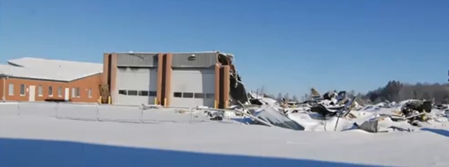
Figure 2: The condition of the building at the time of the investigation
Initial observations
Due to his familiarity with the building and the ignition point, the Fire Chief directed his crews to preserve the garage bays for fire investigation purposes. Figure 3 shows a fire pattern in the vertical metalwork, which seems to center around a hole for the outlet of a radiant tube heater.
It appeared that the hole was related to the fire, but we received information that the radiant tube heater was not operational before the fire. The hole can be seen on the top right corner of the left garage door.

Figure 3: The garage bay after the fire.
Figure 4 below shows the side of the building. We saw damages at the top of the wall, but we did not evaluate the rest of the building. The location of this damage indicated that the fire possibly started higher up.
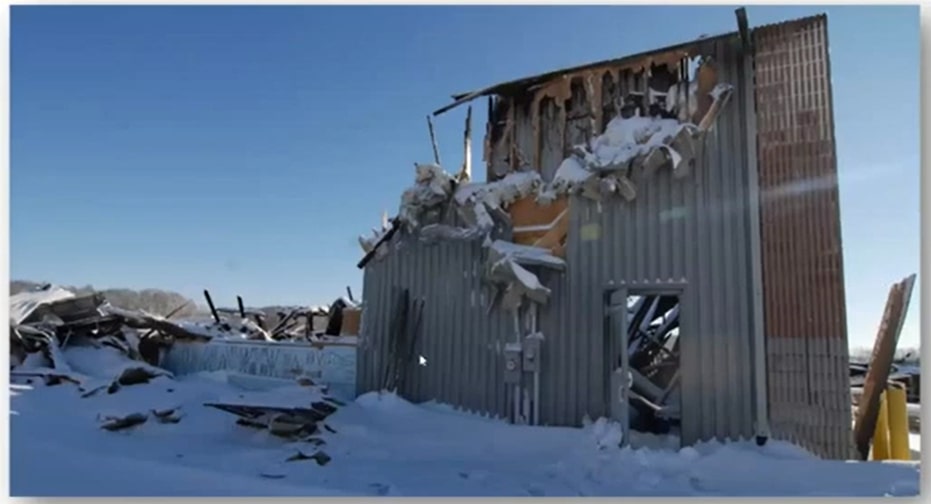
Figure 4: What remained of the left corner of the garage bay.
Preliminary findings and analysis
To get a clear view of the garage doors, we removed the remaining part of the roof using heavy equipment. This helped us visualize the fire damage in the area.

Figure 5: The area where witnesses first saw the fire.
The metalwork on the overhead garage door was still there despite physical damage. However, the wood structures behind the metalwork with the insulation were gone (figure 5).

Figure 6: Fire Department TIC images.
The Fire Chief provided the Thermal Imaging Camera (TIC) images in figure 6. TIC allows firefighters to find out where the most significant amount of heat is to concentrate their efforts on fighting the fire in those areas. The left-hand side image is looking towards the top of the garage door.
The scale on the side of the image shows the corresponding color and temperature. For example, on the scale in figure 6, anything dark is under 150ºC. Any area above 150ºC turns yellow. As the temperature goes above 300ºC, it turns orange, then red when it exceeds 450ºC. The deep red areas indicate that the temperature there was 650ºC.
The little square in the middle of the picture shows the actual temperature that the infrared camera was reading (382ºC). Through the TIC images, we observed that the top and middle plates were burning intensely during the fire.
The combustion chamber for the radiant tube heater and the exhaust tube connected to the hole above that garage door was gray, indicating that they were not hot. It supported the assumption that it was not operating before the fire. We probably would have seen some residual heat from it if it were working.
The image on the right in figure 6 shows the same area after water was poured over the fire. There was a significant decrease in temperature in the fire’s origin, although some residual heat was still above the ceiling. These images were instrumental in providing origin information for the fire. These are not the only two images that we received. There were images of the rest of the building, but this was the only area that contained high heat, meaning it was the fire’s origin.
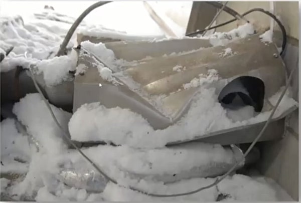
Figure 7: Remains of the combustion chamber for the radiant tube heater.
We examined the entire remains of the radiant tube heater and found no evidence of failure or heat patterns. We also looked at the electrical systems to search for potential electrical causes. Our examination of all the electrical wiring in the origin area did not reveal any evidence of failures.
Conclusion
It was reported that the garage door was repaired on the evening before the fire, and an arc welder was used for welding the track to the angle iron metal piece against the door. Arc welding heats steel to melting temperatures and emits sparks and molten slag, a competent condition source for several building materials used in this building.
After considering all the potential ignition sources, we concluded that the most likely competent ignition source was the arc welding that the contractor conducted on the evening before fire discovery.
Lessons learned
- Be systematic in your investigations.
- Stick to the process.
- Consider all the hypotheses.
- Go through the process of elimination.
- Utilize all sources of information.
Case study 2: Condominium complex explosion

Figure 8: The condominium complex before the explosion.
An explosion occurred in a two year old, nine story condominium tower. The explosion happened in the parking garage, which was extended beyond the perimeter of the high-rise building. The total property loss was over $10 million, and over 200 unit owners were out for months while the building was being repaired.
At about 2:27 am, the superintendent, who lived in the downstairs units close to the garage, heard a huge bang. Six seconds later, there was a second colossal bang. He saw his wall and floor shapes bulge inward towards him, and the floor and walls shook. Several fixtures on his wall fell, and the electric power to his unit went off.
Initial observations
The explosion appeared to have carried through several areas in the building. An inspection of the roof revealed air vent duct deformation from the blast. Additional physical damages included:
- The toppling of concrete block walls in the main electrical room in the garage.
- Fire doors were blown off their hinges in the garage and several stairways.
We initially thought that this was a diffused gas leak or explosion. However, the pad-mounted transformer that fed the building was located outside, near the garage. In addition, there was an underground duct bank from the transformer that conveyed power underground through the sidewalk into the building and the garage area.
The fire scene had been investigated before our investigation by the Office of the Fire Marshal, and they removed the transformer for a better view of what was under it.
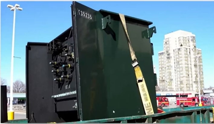
Figure 9: The removed pad-mounted transformer.
As indicated in figure 9, the transformer housing had significant deformation after the explosion. The doors on the front of the transformer were blown off and ended up about 100 feet away.
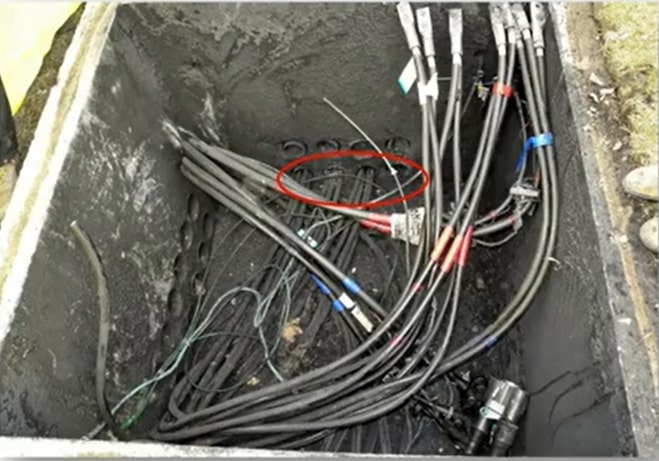
Figure 10: The uncovered transformer pit.
We uncovered the pit over which the transformer was mounted (figure 10) in the hole where the primary and secondary cables connected to the transformer. The secondary wires, which were on the low-voltage side, were 600 volts. The low voltage side had four feeds into the building through four 4-inch diameter ducts. One of the ducts was already pulled out by the Office of the Fire Marshal for Inspection.

Figure 11: Duct 1 conductors
The Fire Marshal’s Office placed conductors from the transformer pits on the sidewalk for further inspection. Our initial examination showed different areas with a bit of heat damage and a soot coating outside the insulation on the conductors.
Preliminary findings and analysis
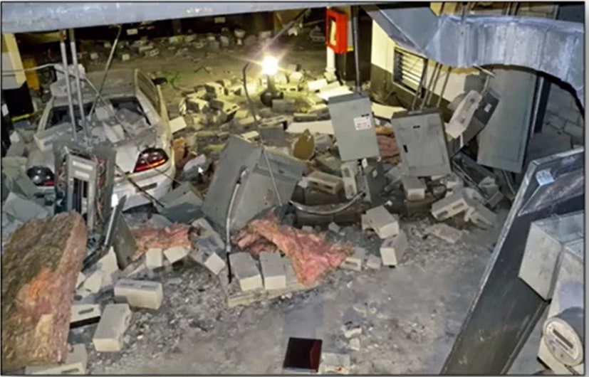
Figure 12: The main electrical room in the P1-level parking lot.
The concrete block electrical room wall was blown out from inside the electrical room outwards. You can see the debris field in figure 12. The projectile distances of the concrete block walls were 50 to 75 feet away. Some of the pieces of electrical equipment were hanging from their conduit, and wires were damaged. The switchboards were also damaged (figure 13).
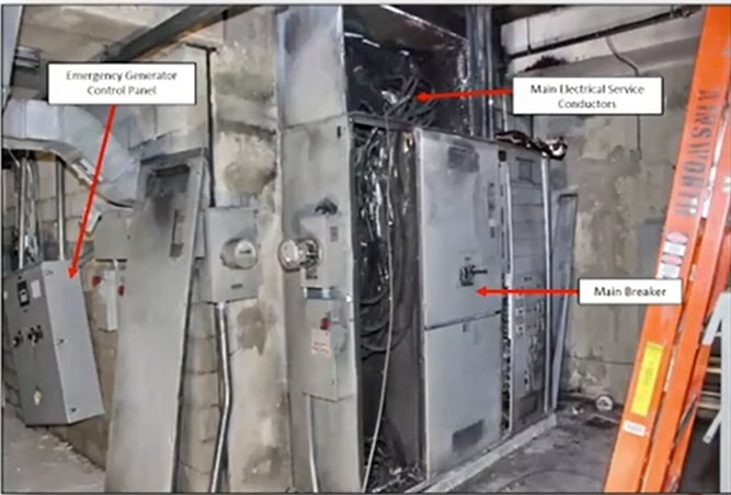
Figure 13: The switchboards on the opposite wall of the electrical room.
The building also had an emergency generator whose control panel got pushed off the wall. You can see this control panel on the left-hand side of the above image. The conductors, also marked in figure 13, came in from the transformer outside and connected to the main breaker.
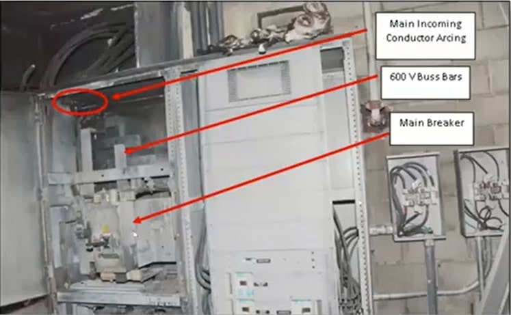
Figure 14: The main breaker and main breaker incoming 600V bus bars.
Figure 14 looks at the incoming conductors through the duct bank from the outside. They connected through the main breaker. Below (figure 15) is the Plan View of the electrical room. The blue lines represent those four incoming busbars that bring power from the transformer. They come into the back of the electrical panel board. The yellow line represents the electrical room outline.
The red arrows are explosion vectors that we placed. The size and direction of these explosion vectors signified the direction and intensity of the push from the explosion.
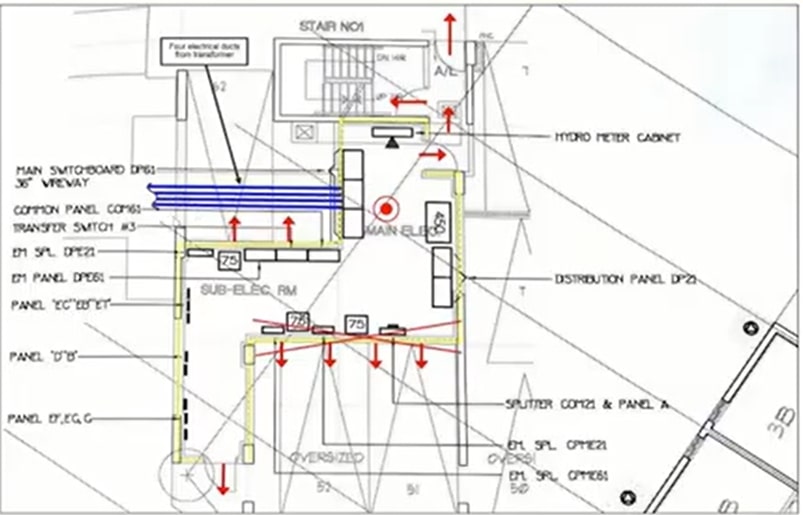
Figure 15: Plan View of the electrical room.
The explosion vector study determined that the explosion originated inside the electric room because the walls were pushed outwards. In addition, we noted doors that were deformed towards and into the staircase on the top side of the electrical enclosure. That staircase went up to the roof, and doors were deformed at the roof level as well. This information further confirmed that the explosion’s epicenter was the electrical room.
Now that we had the explosion origin, we wanted to determine why the diffuse gas was in the electrical room. We considered that it could have been from a leaking propane cylinder stored in the garage or a propane-powered vehicle in the garage that released flammable gas. However, we did not find evidence of propane-powered vehicles or propane cylinders.
We also considered that the explosion might have been caused by sewer gas. The electrical room had two floor drains in it, and sewer gas migrating through the floor drain in the electrical room could have collected in there and ignited from a switch, resulting in the explosion. But we know that floor drains contain traps. Typically, water in the traps can seal any migration of those sewer gases through the system.
Our investigation led us to the sprinkler room, which contained the trap priming system for all the P1 and P2 level area floor drains. All floor drains have a device that dribbles water into the floor drain and keeps water at the base of that floor drain that fills the trap and stops the migration of sewer gases. This building had a similar system, which is a building code requirement.
The flush tanks in figure 16 fill and automatically flush the water down into the manifold. Next, the manifold leads to other smaller lines that convey water. Each line goes to each separate floor drain and keeps that floor drain primed with water, which doesn’t allow the sewer gases to migrate.
Our examination of the floor drains, and the system revealed that it was all working correctly, eliminating sewer gas as the fuel for the explosion.

Figure 16: The main sprinkler room in P1 with trap priming systems.
The garage’s exterior wall facing the transformer had a concrete haunch that showed physical damage. This concrete haunch had four ducts coming in from the transformer outside and then up through the ceiling space to the main switch in the electrical rooms.

Figure 17: The north wall concrete haunch, showing soot and physical damage.
We pulled the rest of the conductors out of the other three ducts. We found a polyurethane foam that was stuck to the conductors. We measured where the foam would have been when the conductors were inside the duct, and we found that it was at the concrete wall inside the building, near the damaged concrete haunch.
Once we pulled the conductors, we shot an RF duct camera inspection video. It involved sending a drain camera into duct bank three.
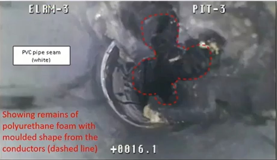
Figure 18: A still frame from the duct camera inspection video.
The dotted line in figure 18 outlines where the conductors were. We considered that the foam may have been polyurethane foam injected by contractors underneath the concrete slab of the sidewalk near the building. Keeping that in mind, we conducted Megger insulation testing on all the conductors we pulled out of the duct banks. A Megger test checks the insulation integrity on electrical wiring.
We put the conductors into a pool of water and applied a voltage of 2,500 volts from the Megger, and the Megger indicates whether that insulation is intact or not. The Megger test showed a breakdown of the insulation.
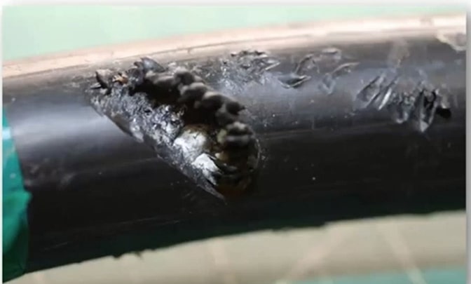
Figure 19: A microscopic image showing insulation damage.
We found spiral damage on the conductor. The aluminum strands within the conductor were exposed. The red phase conductor from duct three also showed spiral damage. We found similar damage on other conductors.
Finding this damage and the form, we excavated the conductors entering the P1 garage level through the concrete haunch. We didn’t find any foam beneath the sidewalk. So we started removing some of the concrete from the concrete haunch and found drill holes. Figure 20 (right-hand image) shows a close-up of the drill holes.

Figure 20: The damaged concrete haunch.
Conclusion
The drill holes had a stiff plastic applicator with foam inside. We found that after the construction of the building, the garage had water infiltration issues from a high-water table. So, the general contractor hired a subcontractor to waterproof the garage walls. The easiest way to do that was to drill holes from inside the garage to the outside and inject hyper hydrophobic foam, a polar polyurethane foam product.
During the process, the subcontractor also drilled through the concrete haunch, not knowing there were electrical cables inside. Unfortunately, in doing so, he damaged some of the wires with the drill. Over time, water entered the transformer pit, made its way through the conduit, wetted the area where the conductors were damaged, and while the water was making its way through the ducts, it picked up impurities. Those impurities included salts, dust, and other chemicals that made the water semi-conductive.
We concluded that the explosion was a result of electrolysis. Electrolysis is the separation of water molecules by using electricity. For example, H₂O is separated into hydrogen and oxygen by applying electricity to water. In this case, some electricity was lost into the water from the damaged cables. As a result, it generated gaseous hydrogen and oxygen. The two gases filled the electrical room and the transformer until the concentration of the two gases was sufficient to ignite a tiny spark from the activation of a switch. It caused the explosion.
When we looked at the rest of the garage, we found other walls with similar drill marks. The foam filling the walls in these areas was parched over and painted.
We concluded that the drilling conducted by the subcontractors damaged the incoming cables, which resulted in the leakage of electricity through water in the bus ducts, and the generation of flammable gases that eventually ignited and caused significant property damage from the explosion. The circumstances indicated that the general contractor was responsible for the loss.
Lessons learned
- Stick to the process, even in complex losses.
- Be systematic in the investigation.
- Follow up on all your leads for the evidence presented in the investigation.
A Litigator’s perspective on experts
Courts are usually not interested in opinions; they value facts and expertise. However, exceptions are made for expert testimony subject to several criteria being satisfied.
An expert’s opinion must be relevant, and its prejudicial impact on a party must not outweigh its probative value. It has to be necessary to assist the trier of fact, meaning it has to be outside the experience and knowledge of a judge or jury. There has to be an absence of an exclusionary rule of evidence, and of course, the expert has to be adequately qualified.
Scene investigation – Retaining your Expert.
In our line of work, it’s essential to pick an expert with proper qualifications. If you have a nuanced case, you must be careful about the expert you’re selecting. If you bring an unqualified expert witness to court, you risk having your entire case fall apart. So, take your time to find the right expert with all the necessary qualifications. The following steps will come in handy when you search for an expert:
- Involve your experts early
Get your expert involved as early as possible in your investigation. It is especially crucial during a fire loss as it will help you avoid scene spoliation. In addition, the multiple parties involved in such cases can lead to scene disruption. As such, it is incredibly crucial to get your expert out there as soon as possible.
- Look for experts with multiple competencies
When retaining an expert, you need to conduct a cost-benefit analysis. It means you need a multi-skilled expert for any case. Your expert must have the competencies that you need to deal with causation, whether it’s a fire loss or mechanical failure.
Competency is particularly essential for fire loss cases because the first arrival to a scene is the best time to gather evidence. Therefore, your expert must have competencies that go beyond investigating causation. For example, they must meet with witnesses, conduct additional research, find the area of origin, rule out electrical fault, or find smokers’ materials that have been carelessly discarded.
- Manage your cases
If you’re working at a desk and only deploying the resources, you need to manage your cases exceptionally well. For example, it is essential for first-party property adjusters investigating a loss because they usually send an engineer to deal with causation.
Get the engineer you retained to meet as many people as possible, get as much information as possible, and gather all witnesses’ names and contact details. Work with your investigator and emphasize the importance of gathering all the necessary information for the investigation. If it’s a significant enough loss, spend the money required to have them do additional work. That will help you gather evidence because scene investigation is critical to any case.
- Invest in your expert
Utilize and invest in your expert at the outset to help you understand the technical aspects of the case. Using the tools at your disposal and investing extra time to communicate your expectations is beyond invaluable in the long run. If you’ve got the resources and a case that’s worth enough money, invest in it. And your expert is your best investment. Build your knowledge and understanding of the case at the time of the loss if you can.
Desk reviews
All is not lost if you can’t retain an expert to attend a scene. You can have an expert for a desk review of all relevant evidence available. That would include scene investigation photographs provided by the other party, Fire Services records or other records of participating experts, information obtained from your insured, and witness statements from others.
Case study 1: Industrial fire loss spread case
This case was settled five or six years ago. It was an industrial fire spread case. Our insured had a neighboring industrial facility beside the fire. There was a lot of damage at the scene, making it difficult to gather evidence. A suspected halide light failure in the warehouse is pictured (figure 21).
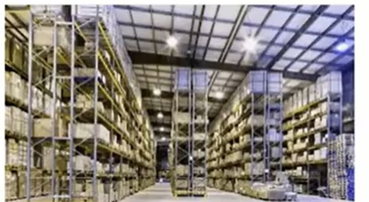
Figure 21: The warehouse
Preliminary findings and analysis
Our expert, on the scene, interviewed an electrical subcontractor who disclosed that installation had deviated from the permit drawings. They hardwired halide lights so that they could not be turned off. It was on the owner’s instructions. Halide lights are to be turned off at least every seven days for 6 hours to prevent overheating and accidental explosions.
Resolution
The deviation from permit drawings meant the halide lights were permanently energized. That fit in perfectly with the theory that one of the halide lights exploded, and hot filaments landed on cardboard boxes stored in the warehouse, thereby causing the fire. And so, we ended up settling that case. So, that one piece of information our expert gathered on the scene got us a settlement.
Scene investigations – Documenting the scene.
Documenting the scene might seem prosaic and unimportant, but it is a critical component of scene investigations. I have seen more than a few cases where there is no proper context for the entire scene that you’re dealing with.
It is essential to document the scene to provide as much spatial context as possible. Take a wide-angle shot from a distance, with more pictures as you approach the stage. That way, different areas of interest can be put into photographic context. If you need to retain an expert subsequently for a desk review, they will be better positioned to understand the scene.
Communicating with your expert
Assume that all your communications with your expert will become part of the record. We all deal with people regularly and often establish relationships to have nonprofessional discussions. However, it is crucial to avoid overly friendly communication when talking to your expert.
Keep your communication professional because it will likely be produced. If there appears to be a friendliness between the adjuster and the expert, it creates an unnecessary opening to challenge the expert’s impartiality.
If you have a statement that has been obtained during your investigation, do not produce the statement to your expert unless you are willing to waive privilege. The purpose of a statement is to refresh your client’s memory when you potentially re-interview them years later. Unfortunately, when stating you’re insured to your expert, you waive privilege, and that can never help your case.
Only take the critical parts of the statement that you want your expert to rely on to work around that. Then, in your instruction letter to your expert, tell them which facts to rely on when preparing their opinion. Then, you document those facts, which must be proven at trial. But privilege will be preserved, and your insured won’t be cross-examined on their statement.
Managing the scene before expert arrival
Preserve the scene in situ before your expert arrives. Ensure that whoever you instruct knows to preserve evidence until your expert arrives. You will not be explicitly faced with destruction, but you will have compromised proof, which is almost as bad.
Case study 2: Large fire loss
A cottage property in Muskoka experienced a significant fire loss. The property had a few elevation changes, and power was supplied underwater through a cable to a transformer. The energy from the transformer then went to a meter. A cable was laid to the panel inside the cottage from the meter.
The previous investigators concluded that the loss resulted from our client’s agent hitting the main power cable while undertaking final grading with a backhoe. As soon as he hit that meter, the place went up in flames, and the cottage was damaged entirely within half an hour.

Figure 22: Images of the scene
When we received the file, investigators prepared a final report based on one site investigation by investigators for each party the day after the loss. Evidence suggests that the power cable had been buried at an appropriate depth with caution tape at the proper level, but it was not determinative.
We were not convinced that the experts had covered all bases during the initial investigation. There were three or four different experts who had been retained by the builder, electrician, electrical subcontractor, our client, and the TSSA. All these experts were huddling around where the backhoe hit the power.
They all confirmed that the builder was present during the investigation. And he insisted that the insured had changed the elevation since they built the house. Granted, the insured elevated a parking lot since it was too steep. But that didn’t change the grading around the property, meaning it would have no impact on the cottage or surrounding areas.
Initial observations

Figure 23: A picture of the cottage before the fire loss
The circled part of the cottage in figure 23 shows the cable. The photo was taken in October 2010, and the cable was coming out of the foundation.
Below is a picture taken a bit later, after the builder had returned to put topsoil over the cables. We could tell from the surroundings that both figure 23 and figure 24 were captured in the same year’s fall. From figure 24, we could determine that the cable was not 18 inches below grade.

Figure 24: The cottage after topsoil was placed over the exposed cables.
When we showed the images to our client, he said none of the experts spoke to him, even though he was at the property with them. He said the cable was three inches or less below grade. The builders did not bury the cable to the proper depth. We realized that the initial report was premature and asked for the discovery evidence.
The scene photographs only contained specific areas. No wide-angle shots were showing the contour of the land.
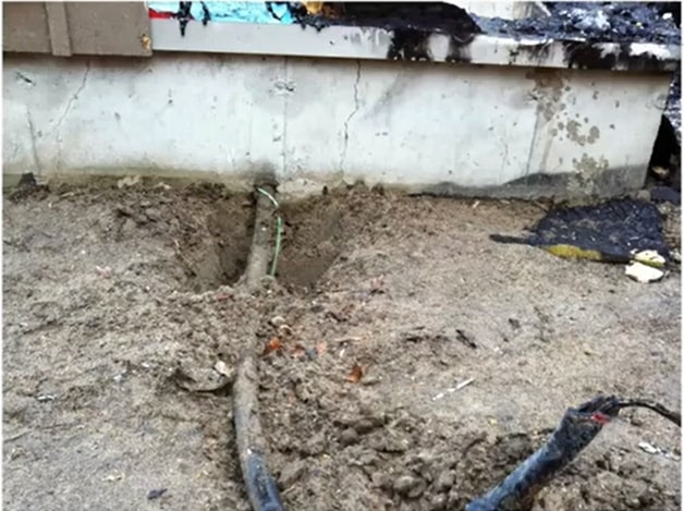
Figure 25: An image showing the cable after the loss.
The image in figure 25 was taken after the loss. There had already been some disruption, but the cable looked close to grade.
Resolution
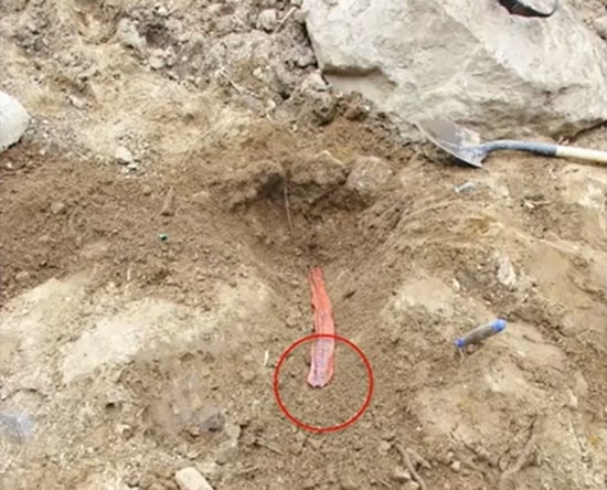
Figure 26: The caution tape.
We also found a photo of a cut caution tape taken when all the experts were investigating. When we asked the builder about the caution tape, he said the cable was buried and suggested that our client cut the caution tape while regrading his home. When we looked at more of the discoveries, we found an image with the cable tied up in a bit of caution tape. The cable had already been buried.
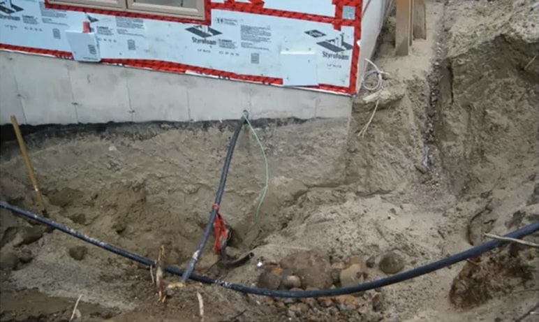
Figure 27: The dug-up electric cable with a pipe beneath.
When we asked the builder about this, he said the electric cable was dug up to lay a sewer pipe beneath it. So they had to dig up the entire area to lay the pipe, including the area with the electric cable. So when we presented all our findings to our expert, we managed to get a reasonable settlement. We took a case that would be closed, and we got a payment of approximately $500,000.
In Complex fire claims, small things can have a magnifying impact on the case as it moves forward. Therefore, you must not rush into things; give your expert wide latitude. But, most importantly, work with your expert. Communicate frequently and get your information early. If you understand your case well, you’re going to be the best asset you have to predict whether you’re going to have a recovery or a good defense to a claim. And the best way to do that is to leverage your experts’ expertise, scene knowledge, and evidence.
Origin and Cause: Choice Experts for Fire Claims and Property Damage
Our forensic experts have extensive experience conducting investigations, preparing reports, and testifying as expert witnesses in court. If you’re dealing with fire failure resulting in complex claims and property loss, call 1-888-624-3473 and we will conduct a thorough inquiry based only on facts and evidence.
An Overview of Complex Material Failure Claims
There is no exact definition for “complex claims.” They come in different shapes and sizes, usually involve multiple stakeholders, and are more challenging to investigate.
Materials Failure Modes
Every material, component, appliance, or system is prone to failure. However, there are only five different modes in which metallic materials can fail, namely:
- Fracture – The separation of an object or a material into two or more components under the action of stress.
- Fatigue – The weakening of the component or material caused by cyclic loading that results in progressive, brittle, and localized damage.
- Wear – Mechanically induced surface damage results in the progressive removal of material due to relative motion between that surface and the contacting substances.
- Corrosion – The dissolution of the material, consisting of oxides built up, rendering the product useless or leading to failure. All metals and alloys are subject to corrosion.
- Creep – Also referred to as cold flow, the permanent deformation increases under constant load or stress.
Why Failures Happen
While the failure modes of metallic materials are limited to five, there is an infinite number of causes for these failures. These can be classified in several categories, as outlined below:
- Service or operating conditions
If operating conditions are not ideal, the system will be prone to failure. Conditions such as the ones outlined below could cause material shortcomings.
Harsh environments: If subjected to very extreme conditions, the components of a fire suppression system in an automotive paint booth could fail in a short time.
Improper operation of valves: If the operator mixes up the valves.
Personal injuries: Abuse of tools can lead to personal injuries. Recklessness can also cause personal injuries. For example, a negligent person was cutting truck rims with a saw, and when he reached the tire, the saw bounced back, kicking him in the face. Operational conditions can cause even more personal injuries. For example, a wheelchair tipped over while a person rode it. Our investigation determined that radio interference from a nearby radio station with an electrical motor caused the operator to lose control of the wheelchair.
Corrosion: Corrosion can lead to failure, especially in metallic materials. We have seen a corroded cooling tower at a hospital. The legs were rusted, and the tower was in imminent danger of collapsing.
- Improper maintenance
A lot of components and systems need to be well-maintained to function correctly.
Example 1: If gears or bearings are not lubricated, they go into lubricant starvation, leading to accidents. An example of this is the collapse of wind turbines and cranes.
Example 2: If the bolts of a wheel are not properly torqued, the wheel can separate from the axle. If the maintenance is not done according to the applicable regulations in a fire suppression system, that system could fail.
Example 3: Residential fuel storage tanks can leak if they are not maintained according to the applicable code. They can fail due to internal corrosion.
- Manufacturing deficiencies
Most manufacturers try to produce a defect-free product, but they don’t always succeed. Sometimes, defective products can end up in the market. For example, casting and welding deficiencies could lead to failures. There are various reasons for manufacturing deficiencies. For example, a defective aluminum ladder caused a permanent injury to a roofer who fell while he was climbing it because the ladder had defects in its castings.
An example of failure resulting from improper chemical composition can be seen in the case of a commercial pizza oven explosion. The oven exploded on first use because the stones were made from improper material.
Packaging and finishing issues can also lead to failures. For example, we have dealt with a case that involved chocolate contamination. The packaging of the chocolate was not made according to the applicable standards, and the substandard package caused contamination.
A manufacturing deficiency led to a personal injury involving a paddleboard. When the person using the paddleboard tried to climb on it, he scratched his chest because the paddleboard had manufacturing defects resulting in an improper finish.
- Design deficiencies
In our investigations, we encounter design deficiencies. A few examples are:
- A video screen collapsed at a theater in downtown Toronto because the latches holding the video panels were substandard.
- We regularly encounter plumbing components and appliances that have design deficiencies.
- Design deficiencies could lead to personal injuries. For example, a miter saw that had no safety pin, caused the blade to drop and cut the user’s fingers.
- Installation issues
Installation issues are a leading factor for failures. For example, if the system is not installed correctly and there is no insulation in a fire suppression system, that system could freeze during winter.
Example 1: In a water treatment plant, the constructor chose the wrong type of coupling in one of their systems, and that coupling corroded within days, creating significant damage.
Example 2: We have seen a locomotive engine fire caused by an improperly installed hydraulic hose.
- Wear and Tear
Naturally, materials and components can become worn, primarily due to aging. One example is equipment aging, which was seen in the case of tahini paste contamination. An old pump caused the contamination because particles from the rotors ended up in the product.
Another example is a leaking oil pump. All the gaskets were brittle and dry, allowing oil to escape, leading to considerable environmental damage.
- An Act of God
Sometimes, extreme weather conditions such as ice storms, natural disasters, and windstorms can lead to failure.
- Negligence
Some people are negligent, and their actions could lead to significant incidents. For instance, some people don’t turn the thermostat high enough during winter. As a result, the pipes freeze when nobody is home, leading to floods.
Example 2: Frequently, when a residential oil storage tank is located indoors, it is overfilled because the driver who is delivering the oil is not paying attention to the equipment. This, too, can lead to failure.
- Insurance fraud/ breaking and entering/ revenge
We have seen intentionally flooded homes, in an attempt to get insurance money. We have seen orchestrated break-ins so people could claim money for personal belongings. We have also seen improper use of rented hardware tools where people intentionally got hurt to claim that the tool was defective.
Basic steps in failure analysis
Although each investigation is unique, the basic steps are the same. To complete an investigation, forensic engineers should take note of these essential steps:
- Gather as much background information as possible, including photos, maintenance records, inspection records, and repairs, if any.
- Try to get an understanding of the circumstances of the event. If possible, interview all the parties involved, such as owners, operators, contractors, and witnesses.
- Organize your investigation and conduct it thoroughly. Make a list of tasks you must complete to avoid losing track of what needs to be done.
- It is essential to identify the components of interest for the investigation and document their condition, environment, and relationship with each other.
- Obtain permission to remove components and document the procedure.
- Prepare a proper chain of custody because more clients or opposing experts are inquiring about the chain of custody. Prepare a chain of custody from the moment you get components from a site to the moment you bring them to the lab.
- Initially conduct preliminary and non-destructive testing and examination.
- Discuss preliminary findings and further course of action with the client.
- If a joint destructive examination is required, prepare a testing protocol. Circulate it with other parties and allow them to discuss the testing protocol.
- Organize the testing and lab examination.
- Analyze the gathered data and determine the root causes of the failure.
- You have to compare data with applicable standards, codes, or regulations in many instances.
- Discuss findings with the client.
- Prepare a formal report, if required.
We have been involved in several complex failure analysis investigations. Below are a few case studies showing practical applications of the above principles.
Case Study 1: Collapse of a Grain Silo Spout
A grain silo spout collapsed and spilled grains to the ground,and we were asked to determine the cause of the incident. This image was taken by the homeowner shortly after the incident occurred. Fortunately, nobody was hurt.

Figure 1: The collapsed grain silo spout
The elevators in the grain silos were only a few years old, and the failure occurred without warning. By the time we were assigned to this claim, the site condition had changed. Most of the components were removed for storage, and we could not see their layout on site. When the site is cleared quickly, it makes our work more difficult.
The structure was unstable, so it was difficult to climb it to see its condition at the top. Therefore, we retained the services of industrial climbers and guided them via radio to take essential photographs. This was before the availability of drone technology.
Initial observations

Figure 2: Deficiencies noted, including crisscrossing cables
As indicated in figure 2, there were a few deficiencies, like crisscrossing cables, turnbuckles crossing, and cables rubbing against the top of the lift. However, the evidence was already in a shed, where we had the opportunity to examine it in the presence of representatives from the manufacturer and installer.
We needed to identify the various components and determine how they were installed. Following this preliminary examination and identification, relevant evidence was collected and brought to our facility for further review.
One item of interest was the retarder, a specially designed box that slowed the speed of the grains, thereby preventing them from being crushed. Each spout was provided with a retarder, which had two pipe sections welded on each side. The spout was also installed on-site using welding. Therefore, it had two different welds. One was the manufacturing weld done at the factory, and the second weld was done by the installer on site.
The factory weld was of interest to us. You can see one of the pipe sections at the end of the retarder. We looked at the factory weld and marked locations where samples of interest could be cut and used for further examination.

Figure 3: The factory weld with marked locations
Preliminary Findings and Analysis: The Turnbuckle
Another item of interest was a broken turnbuckle. We wanted to determine whether it was the triggering factor in the failure or the effect of the incident. A turnbuckle is a device for adjusting the tension or length of cables. They are designed to take only longitudinal loads. So, bending the turnbuckle on the fracture area suggests that the turnbuckle was subjected to lateral loads.
We also noted that the threads were crushed in the section where the turnbuckle was compressed. In a fractured component, fracture surfaces are usually mirrored images of each other. Therefore, we retained a small sample from the turnbuckle and took it to a Scanning Electron Microscope (SEM).
The SEM allows examination of components to magnifications up to 30,000 times or higher. In addition, the images obtained under SEM showed cleavage facets, which indicates that the fracture was trans granular.

Figure 4: SEM images of the turnbuckle sample
Figure 4 shows no manufacturing defects that indicate that the turnbuckle has an issue. Further, we conducted a metallurgical evaluation of the turnbuckle. This evaluation was done in the longitudinal section. We examined the microstructure under an optical microscope, and we did not see any gross metallurgical deficiencies.
The microstructure was typical for steel that is commonly used to make bolts. Chemical analysis indicated that it is made from carbon steel, which is also typical for turnbuckle applications. Based on the examination of the turnbuckle and the results obtained, we determined that the turnbuckle was not the cause of failure.
Preliminary findings and analysis: The weld samples
One could see an excessive weld at the bottom from the weld samples we selected for examination. The low part of the microscope images shows that the weld did not penetrate throughout the entire wall.
The weld exhibits a deficiency called incomplete weld penetration. The fractured weld was taken for examination under SEM. Relevant features which were not visible by the naked eye were observed. As indicated on the right-hand side image in figure 5, the weld had a lot of pores, and incomplete weld penetration was confirmed.

Figure 5: SEM image of the weld
Porosity in any material is undesirable because pores can act as stress concentrators and reduce the load-carrying capability. However, welds are very complex structures. Therefore, when we analyzed the weld’s microstructure, we found porosity.
Conclusion
We concluded that the spout collapsed because of manufacturing deficiencies, namely a substandard weld. Other factors added undesirable stresses to the structure. The crisscrossing of cables caused by an installation deficiency and ice buildup due to weather conditions contributed to the failure. However, these factors acting alone could not have caused the collapse.
The main contributing factor to the incident was the sub-standard weld. Therefore, the turnbuckle failure was not the contributing factor but the result of the failure.
Case study 2: Tower Crane Collapse
A tower crane collapsed at a construction site, injuring the crane operator. Fortunately, there were no fatalities but significant property and equipment damage. Unfortunately, the Ministry of Labor was involved due to the personal injury, making our site access more difficult.
Parties involved
- The crane owner
- The developer
- The crane inspector
- The Ministry of Labor
- The installer of the crane
Initial observations
The crane collapse was caused by the failure of a slew ring, a ring that allows the crane to rotate in the horizontal plane. The slew ring is held in place by 48 bolts. These bolts fractured, causing the crane to collapse. Several bolts were retrieved from the site for further lab examinations. However, not all the bolts were found.
In a tower crane incident, it is essential to retrieve the crane logbooks, including inspection, maintenance, and service. It has particular requirements on how it is maintained and inspected.

Figure 6: Some of the bolts retrieved from the site, labeled for further examination
Preliminary Findings and Analysis
In examining the fractured surface of the bolts under a low-power microscope, we observed that most of them exhibited beach marks, which are always associated with fatigue. The fatigue of the bolts indicated improper installation. When the crane was erected, these bolts were not properly tightened. They were either overtightened or too loose.
Metallurgical evaluation did not produce any evidence of gross metallurgical deficiencies. In addition, chemical analysis revealed that the bolts were manufactured using the required steel grade according to the crane manufacturer’s specifications.
Conclusion
We concluded that the collapse of the tower crane was the result of improper installation on site. The bolts securing the slew ring were not properly torqued, and no manufacturing deficiencies were found in the fractured bolts.
The fact that this crane was over 30 years old at the time of the incident contributed to the failure. The life expectancy of a tower crane is approximately 25 years. Additionally, the crane was imported from Germany, no longer certified. Finally, the operator did not maintain the required logbooks as per Canadian Standard Association, and the crane operator was an illegal immigrant without a working permit in Canada.
Case Study 3: Automotive Part – Tie Rod
A vehicle was being driven on a straight stretch of road when it suddenly went into oncoming traffic, hitting two bikers headfirst. Unfortunately, one of the bikers died.
We were required to examine the vehicle’s components and determine what could have caused the car to lose control. Our focus was on the tie rod, shown in figure 7 below.

Figure 7: The wrecked car (left) and the fractured tie rod (right)
The tie rod fractured completely, and this condition caused the vehicle to go into oncoming traffic and the driver had no control over the steering wheel. Tie rods are essential parts of the vehicle steering system. They connect the steering gear to the wheel using the length of the rod with a ball-and-socket at one end. So, practically, tie rods move from the steering wheel to the wheels.
Involved parties
- The car manufacturer
- The service technician who maintained the vehicle
- The driver
- The family of the two bikers involved
Preliminary findings and analysis
We removed the incident tie rod and took it for examination under SEM with consent from all involved parties. We also conducted the mechanical and chemical analysis, and no gross abnormalities were observed.

Figure 8: SEM images of the fractured tie rod
The most crucial piece of evidence was on the fracture surface. These two images taken under the SEM show a feature called dimples. Dimples are always associated with ductile overload.
Conclusion
Essentially, the tie rod fractured because it was subjected to some sort of stress. It did not fail as the result of a manufacturing defect. There is a saying in material science that the material failed as intended. The component is designed to withstand certain stress. Beyond that stress, it will eventually fail, which will not be the manufacturer’s fault. It will fail because it was subjected to an overload, which is the case here.
Despite the driver maintaining that a vehicle defect caused the accident, he was held accountable for the tragedy because the tie rod failed as intended. If it were defective, the failure mode would be entirely different, as there would be significant tells on the fractured surface to indicate that.

Figure 9: Microscopic images of the fractured surface
The consecutive markings on the left image are called beach marks. They’re evidence of a progressive failure, indicating that the tie rod would have failed because of fatigue.
The appearance of grains on the middle image is usually associated with hydrogen embrittlement. Hydrogen embrittlement refers to when steel becomes brittle due to hydrogen ingress in the microstructure. It’s usually caused by improper heat treatment. The right-side image shows cleavage marks, which indicated that the rod was brittle. However, it was not showing any evidence of a manufacturing problem.
Case Study 4: Chair with Welded Frame
Chairs with welded frames were installed in a public place, and a parent was holding his baby over his shoulder, rocking the chair, when the weld sustaining the seat failed without warning. As a result, the baby fell to the ground head first.
We were asked to provide an independent engineering opinion on the most probable cause for the incident.
Involved parties
- The owner of the place where the incident happened
- The chair manufacturer
- The chair distributor
Initial observations
We collected the incident chair and a few sample chairs for comparison. Each party sent their technical experts to participate in the joint examination.

Figure 10: The seat is supported at the rear using a curved bar welded onto the frame. The close-up on the right shows the weld on a non-failed chair
We considered this a design deficiency because people tend to sway when sitting on chairs, subjected to cyclic stresses. On the incident chair in figure 11, both welds gave way.

Figure 11: The incident chair (left) and the remaining frame with the locations of the failed welds (right).
Preliminary findings and analysis
We documented the frame and welds. Then, we took them for examinations under the stereomicroscope and later under SEM.

Figure 12: Stereomicroscope images of the welds
As shown in the two images above, the bars with the two failed welds showed large porosity and inclusions. One of the welds was taken for examination under SEM, which confirmed the presence of large pores and non-metallic inclusions. We also conducted a methodological evaluation of the weld. The weld appeared to be non-uniform, and it had pores.
Conclusion
We concluded that the accident resulted from a design deficiency and manufacturing deficiency. The matter was settled out of court and in favor of the plaintiff. As a result of our investigation, 800 similar chairs from nationwide locations were removed from service.
Case Study 5: Fire Sprinkler CPVC Pipe Joint Separation
A CPVC in a fire sprinkler system failed in a high-rise residential building, resulting in the separation of the joint separation and fitting. The client wanted to investigate this matter for potential subrogation.
Typically, the piping systems in a residential building are concealed above the ceiling or in the walls. In this case, separated polymer pipes caused flooding that resulted in a collapsed roof. The damages covered over 40 units, the two elevators in the building, the lobby, and some common areas. The damages cost over a million dollars.
Involved parties
- The building owner
- The installer
- The pipe and contact cement manufacturer
- The fire protection company who did the actual installation
Initial observations
The components were secured, and we were provided access to the scene. All sprinkler systems need to be put back in service quickly, so whenever you get one of these claims, you must ensure that somebody documents them adequately.
We inspected the entire sprinkler system and documented its conditions, as well as its settings. It was crucial to examine the whole site because sometimes evidence is not in the secure components; it’s in a broken or separated part somewhere in the incident site.

Figure 13: The separated pipe (right) and it’s close-up (left)
The pipe separated without any warning within the ceiling cavities. The pipe repairs were completed immediately to get the system back in operation and provide fire protection to the entire building again. We realized that the failed pipe joint caused the pipe separation upon examining the components. In addition, our site visit eliminated other potential causes of failure.

Figure 14: An example of a joint connected to a sprinkler head (left) and the separated pipe (right)
The red substance connecting the pipe pieces is the contact cement or glue used to join the pipes and fittings. It’s common for joint sections to separate in systems that use polymer pipes.
Preliminary findings and analysis
During the investigation, we found that the cut end of the pipe was not square. In addition, there was a lack of or inadequate chamfering or beveling of the pipe end. These two are critical installation features. The manufacturer points these out very clearly in their instructions, and for a good reason. There was also inadequate application of the contact cement. It didn’t make proper contact on all the surfaces.
There was insufficient insertion depth, one of the most critical steps. Several factors play a role in the strength of the joint based on how deep it is inserted into the socket of the fitting.
In this investigation, we had to look into the measurements of the components, and review codes, standards, and manufacturer instructions. It helped us develop a hypothesis during analysis. We hypothesized that the cause of failure could have resulted from installation issues or the contact cement being outside the specific area.
We then conducted a joint inspection with the other parties. We sectioned the pipe and completed various tests to determine the root cause of the failure. We used analytical methods such as FTIR and GCMS on the pipe and cement.
 Figure 15: FTIR results
FTIR helped us understand the material components and any deviations from the standard. They also helped us identify possible contaminants of the surfaces to determine if the contact cement was degraded before its use. Finally, we analyzed the leftover blobs of contact cement on the pipe.

Figure 16: GCMS results
GCMS helped us identify specific components and the quantity of those detrimental to the contact cement. However, we did not find any components or deviations that were large enough to support a hypothesis of the contact cement being defective.
Possible reasons for the failure
- Improper installation
- A defective solvent cement or glue
- Defective pipe or fitting
- An excessive internal fluid pressure
The static pressure from the sprinkler system itself or an issue with the pumps that could trigger an instantaneous increase in pressure could have caused the failure.
Conclusion
We found several issues with the insertion depth and the cutting of the pipe. That led us to conclude that the installation was the only contributing factor to the failure and that the installer did not follow the appropriate procedures. Therefore, the improper installation was the cause of the failure.
Case Study 6: A boom lift failure

Figure 17: The failure site
A contractor was working on a boom lift when it suddenly failed. The bucket fell to the ground while the contractor was inside, and he suffered personal injuries. In this case, the focus of that failure was the turntables on the boom lift.
Involved parties
- The lift manufacturer
- The lift installer
- The bolt manufacturer
- The maintenance company
- The contractor who suffered personal injuries
Initial observations

Figure 18: An example of in-tact turntables
The turntables separated because the bolts securing them fractured. The images above show what that would look like upon installation.

Figure 19: A close-up of one of the failed bolts (right) and other failed bolts from the site (left).
Some failed bolts looked very jagged and rough, and others looked smoother. The smooth bolts showed some signs of fatigue. Out of the twenty bolts, only five of them were fatigued. Fatigue can result from manufacturing, design, installation, or maintenance failure.

Figure 20: A close-up of the bolts showing signs of failure
The marks on the left picture in figure 20 indicate a crack, which develops in the material over time. Eventually, the component will lose strength if the gap is big enough. If the crack completes, the bolt will fail by fracture.
Preliminary findings and analysis
We conducted microscopy, metallography, hardness, tensile, and chemistry tests to understand the composition of the bolts. We also ran these tests to look for possible internal issues with the bolts.
We proved that the material was strong enough to resist loads or static loads of the boom lift. In Canada, the standard for steel construction includes safety considerations for loads and reducing or eliminating the likelihood of fatigue.
We reviewed material strength, structural load, steel construction code, and fatigue considerations in the structural analysis. As a result, we determined that the bolts met the requirements for their standard. We also concluded that the boom lift design met the minimum structural requirements for its intended loads. However, it may have failed to account for cyclical loads caused by the vehicle it was mounted on or the loads applied during operation.
Potential reasons for the failure
- Improper design
- Defective bolts
- Improper installation
- Inadequate maintenance
Conclusion
We proved that the material strength was enough but may not have been well within the safety requirements in the structural codes. The fatigue in those bolts was slightly the result of improper torquing during installation. We also considered that the bolts were not re-torqued or were not receiving proper maintenance.
The installer did not include re-torquing the bolts in their procedures. In addition, the contractor, who was supposed to do inspections yearly, did not complete their annual maintenance on this unit. All these factors played a role in the failure, but we concluded that the leading cause of the failure was the inadequate installation and lack of timely maintenance.
Case Study 7: Corrosion of stainless-steel wires in water connectors
A water connector failed due to the failure of the stainless-steel wire braids. Water connectors can create massive damage depending on where they are in the building.

Figure 21: An example of a functioning water connector
Flexible water connectors can be found in high-rise buildings. They’re made of an internal polymeric hose with a braided stainless steel wire on the outside. Sometimes, the inner hose may not withstand the internal pressure by itself. Hence, the braided wire material is added on the outside.
The braided wire material provides strength for these connectors to withstand pressure. It’s easy to presume that stainless steel does not rust or corrode. However, that depends on several factors, including material composition, ambient conditions where connectors are installed, and other chemicals.
Parties involved
- The unit owner
- The manufacturer of the water connector
- The wire manufacturer
- The maintenance contractor
- Property management
- The Canadian supplier
- The installer
Initial observations

Figure 22: The damaged flexible water connector
Figure 22 shows a slight opening on the rubber, and that’s where the water came out. Once the metal wires break, nothing is holding the rubber hose. So, it bulges and perforates.
Typically, three types of corrosion affect the wires on a connector like this, and they are:
- General corrosion – Surface corrosion indicated by brown material that we see whenever steel is rusting
- Pitting corrosion – Shows small surface perforation in the material. It is much harder to see by visual inspection alone, and it typically occurs as a result of some of the chemicals that come in contact with the surface of the wires.
- Stress corrosion cracking – This shows as cracks grow into the wires.
We didn’t see a lot of rust on the connector. However, some rust spots could be seen by the naked eye.
Preliminary findings and analysis

Figure 23: The visual microscope image of the wire (left) and the SEM image (right)
We used SEM for our water connector analysis and a visual microscope for the braided wires. The results showed cracks and pits developing on the wire. There were also a lot of brown rusty surface deposits. It was a clear indication that the stainless steel was rusting away.

Figure 24: A microscopic depiction of the cracks and pits on the wires
We mounted and polished these wires to show how the cracks and the pitting progressed inside. We revealed some fine cracks and pits that weakened the materials and eventually led to the failure. However, as the image above indicates, there wasn’t a lot of material loss, meaning the wires did not experience much surface corrosion. Instead, the corrosion was rapid and invasive, going into the material itself.
Potential reasons for the failure
- Improper material composition
- Inadequate heat treatment during manufacturing
- The storage of harsh chemicals in the vicinity of the connector
- Inadequate maintenance or replacement schedule
The root cause of failure could have been stress corrosion cracking aided by pitting. It points to the hose or the wires being attacked by chemicals that caused the breakdown.
However, there are times when some steps in the manufacturing process are not done correctly, which makes these wires more susceptible to this type of failure.
We showed that the wire composition slightly deviated from what the material specification was supposed to be, which allowed for localized corrosion to develop quickly. It wasn’t wholly different from what it should have been, but it was enough to allow corrosion to start.
The wire showed minor but clear signs of corrosion, and this connector could have been inspected and replaced since it was over ten years old.
The security and the property management could not find the shutoff valve for this bathroom, which was in the common areas of the building. As such, they had to shut off the water for the entire building. This process took a long time, and a lot of water escaped through the building. If property management had better procedures, they could have substantially mitigated the resulting damages.
Conclusion
We concluded that the root cause of the failure was defective material. However, inadequate maintenance was a contributing factor. Moreover, improperly trained personnel contributed to the extent of damages.
When it comes to subrogation involving material failures, identifying other contributory factors is as important as determining the root cause of failure. Identifying all the involved parties requires out-of-the-box thinking and gathering the correct information early in the investigation.
Origin and Cause – An Expert in Complex Claims
Through the journey of this article, we have exposed the various facets of Complex Claims and failure analysis. There are multiple reasons why failure could occur, and our expert forensic team at Origin and Cause is well versed in this domain to provide an unbiased understanding of the claim at hand. Contact us for any assistance regarding complex claims and failures that require expertise. Our team will get to the bottom of the cause through a thorough scientific understanding of the case.
Whenever there is a catastrophic event or recession in the world, our desks are filled with investigations with questionable physical evidence. Since March 2020 (the onset of the global covid-19 pandemic) we have seen the trend come to pass yet again. The last time this had happened – the global financial crisis of 2008.
Anecdotally, some adjusters report that they saw more claims in the first three months of the first covid-19 lockdown in Canada than they had seen in the three years prior.
In keeping with that, the 4th Annual National Tour organized in 2020 – virtually, of course – focused on the investigation of suspicious claims. Five sessions examined fraudulent claims involving break and enter, water loss, fire damage, vehicle claims, and structural damage.
Once again, a thank you to all the participants who joined us for these sessions. A thank you also goes out to all participants who joined us in presenting a different perspective into claims – and helped make these sessions so valuable for adjusters, lawyers, and risk managers alike.
What Is a Fraudulent Claim?
A fraudulent claim is one made for a loss that has been caused wholly or partially by the insured. In some fraudulent cases, the claimant may try to ‘cash in’ on a legitimate loss by trying to claim pre-existing damage opportunistically. In others the insured may have taken active steps to cause the loss themselves.
To make the claim appear legitimate, the insured will try to manipulate the scene of the incident before or after the loss; or weave a false narrative about how the loss occurred.
And that’s where the team at Origin and Cause comes in. We cut through the narrative that is being presented and delve deep into the facts. Our goal is simple – to determine to a high degree of probability causes behind the loss.
Once the cause of the loss has been identified, it becomes clear if the insured has played a role in causing/exacerbating the loss.
What Are the Different Types of Fraudulent Insurance Claims We Investigate?
We are a full-service forensic engineering and investigation firm in Canada. That means we assess incident sites and investigate all types of claims, including:
- Water damage claims
- Vehicle insurance claims
- Break and enter investigations
- Fraudulent structural claims
- Structure fire incendiary claims
Invariably some of these are fraudulent claims. From premeditated actions (leading to the loss) to weaving a false narrative, insureds can try a variety of tactics to make a false claim or exaggerate the value of the claim.
One type of loss we couldn’t discuss during the sessions are boat fire claims. The use of private boats is a very popular pastime in Canada and a lot of people own boats. Watch an earlier marine fire and explosion webinar to learn more about marine fires and fraudulent boat loss claims.
What Is the Role of the Forensic Engineer/Investigator in a Fraudulent Claim?
“A forensic expert needs to look at the physical evidence of every case with no bias and no preconceptions”, says Michelle Bradley, a veteran forensic engineer with over 15 years of investigations.
And this theme is common across all our sessions – as forensic investigators we have to focus on the physical evidence. We don’t factor in the intent of the insured. It is critical not to comment on intent, something that is outside the scope of our investigation.
Whenever a client tells us about the insured’s financial situation or other circumstantial evidence, we reiterate that our opinion will be based only on the physical evidence – anything else will weaken the technical opinion (if taken to court).
Such as an approach is essential for keeping the methodology consistent across investigations. We let the scene of the incident speak for itself, avoiding physical contamination or bias from creeping in.
However, that does not mean we take information at face value. A forensic engineer must sometimes dig deeper into the findings of police and fire reports, sometimes question the statements of the insureds. After all, an insured is not going to be totally truthful if they are trying to make a fraudulent claim.
Fraudulent Break and Enter Claims
Legitimate claims involve burglary, arson, or vandalism. Incidents are investigated through CCTV footage, alarms, and motion detectors. So when ‘burglars’ have been able to rip out a concealed alarm panel within 30 seconds of breaking into an unfamiliar building it sets the ‘alarm bells’ ringing.
Another red flag is when the insured suggests the CCTV system is not set to record, especially when the DVR equipment is present. We have also seen cut communications lines, tampered motion detectors, cameras hindered by unusual placement of content, door contact hardware being defeated, bypassing for alarm zones, and ‘smash and grab’.
Fraudulent Vehicle Claims
Arson and fraud vehicle claims have been on the rise since the onset of the covid-19 crisis. A similar trend was seen in 2008 too. The motive behind a vehicle fire claim is inevitably financial. A common type of incident is when the insured sets fire (or tries to set fire) to the vehicle. This can be if the vehicle is a ‘lemon’ (constant mechanical faults); the insured is unable to afford payments on it; or is trying to make a claim for their business.
In such instances data from the vehicle’s infotainment system and control units is vital for verifying the insured’s version of events. Modern systems can track vehicle movement, opening and closing of doors, maintenance cycles, and vehicle faults.
Another powerful ally for information gathering is Statutory Condition 6 (Insurance Act 1990), requiring the insured to produce reasonable evidence required in the investigation of the incident.
Structure Fire Fraud
There are numerous indicators that can suggest fraud in a structural fire claim. These can be multiple fire indicators; unusual fuel load or configuration; irregular fire patterns; lack of expected fuel load; incendiary devices; lack of expected ignition sources; and burn injuries.
In one fire incident we observed an irregular fire pattern. A ‘protected area’ that looked virtually undamaged could be seen on the floor, and the area surrounding it showed surface heat damage. A similar protected area was found on the bed. It also ran all the way down the stairs. As it transpired, fuel had been poured along the path of the protected area and the fire had been lit. However, the fire burnt out because of a lack of ventilation, leaving behind a telltale sign of arson.
Water Loss Fraud
Claims involving water loss can be difficult to investigate since even fraudulent claims look like real claims. Did a braided hose fail on its own or was it cut deliberately? Did a pressure valve have a manufacturing defect or was it tampered with to cover up another loss? It’s why we rely on X-rays and electron microscopes to determine the cause behind the loss.
Structural Damage Claim
Fraud in structural damage claims arises in two ways: pre-existing damage and opportunistic claims. In case of pre-existing damage, insureds try to slip in unrelated damage with real damage claims. In opportunistic claims an insured may try to claim for instance, loss of inventory due to structural damage, but that structural damage may have been pre-existing.
We receive many requests to investigate wind damage claims. In such cases there is a chance the property owner is trying to pass off frost damage as wind damage. That’s why a ‘big picture’ view of the incident scene is important. Things like damage to surroundings and past attempts to repair similar damage are vital clues.
Signs of Fraud and Where to Find Them
What do we see, or not see, at a scene? That’s what we put in our reports. Witness statements, fire department and police reports, service/maintenance history, before and after photographs of the event, can all indicate a fraudulent claim. As forensic engineers we need to know how the loss occurred, not just the mechanism of the loss.
Imagery from electron microscopes; video footage from doorbell cameras, dash cams, and social media; and witness statements all aid the investigation of a claim.
Time Is of the Essence
Time is of the essence in investigations and incidents must be investigated promptly. In part to make sure the physical evidence is available and isn’t disturbed any more than necessary; in part because it helps the insurance company make a more informed decision.
Timely assessment by an investigator before payment is made by the insurance company is extremely beneficial for the insurer. Before the claim is paid out, the insured is under a statutory duty to provide a lot more information, than once the claim has been approved.
The sooner you can ask questions of the insured, the sooner you can get the best information. Right at the beginning is when they are most motivated to help you and give you the information you need. Once the insured retains legal counsel or the insurance company has made payment, it can become very difficult to get information.
We hope you found our sessions informative. If you have any questions or would like to know more about investigating fraudulent claims, feel free to speak to us. We are more than happy to take your questions.
No matter the type of claim – whether a machinery failure, structural collapse or electrical malfunction – the origin and cause can often be traced back to the failure of a single piece of equipment or component. While the component may be small, and the failure mechanism microscopic, the resulting damages are quite the opposite. Catastrophic losses totalling millions of dollars are not uncommon, and all stemming from a single, seemingly small failure.
For the 6th Annual National Tour, a multi-disciplinary group of industry-leading forensic experts delve into and discuss Equipment Failures and Component Malfunctions and show why these claims are greater than the sum of their parts.