Failures and failure analysis
Several factors contribute to the complexity of structural claims. Complex structural claims typically involve a partial or a total collapse. Often, it’s not easy to determine the cause of the failure. Identifying the root cause of structural collapses requires expert analysis beyond a simple visual inspection of the structure.
Therefore, it’s no surprise that multiple parties would be interested, and the different parties will try to deflect the blame. However, various factors often contribute to structural failure or extensive damage. In addition, it’s not unusual to see that those factors reveal a latent defect that was at the heart of the collapse.
What to look for in a complex claim
Building safety and security is paramount in all claims, including complex ones. Therefore, a structural engineer should be retained from the beginning to assess the site and give instructions on safety measures.
Obligations under orders to remedy unsafe buildings – When there is severe damage, the city usually issues an order to fix a dangerous condition. Under that order, there is an obligation to retain a structural engineer to assess the site and give safety instructions.
Preexisting conditions’ impact or role is widespread in large losses. Preexisting conditions can cause structural deterioration and poor detailing, amongst other failure modes.
Mandatory code upgrades – When severe damage requires significant repairs or reconstruction, it must be upgraded to the current code. Otherwise, it will be unsafe.
Additional building permit requirements – These are needed if the footprint of the building is changed. Different permits will be required for different types of buildings.
Small changes that may lead to complex approvals – A footprint change requires approval. If the services are replaced, like a track or septic system, you need to get approval from the relevant governing bodies.
Document management in complex structural loss
- Collect documents early
- Be thorough
The documents in a complex structural loss differ from documents in other claims. There are numerous documents in construction matters. Therefore, it is crucial to collect documents early and be thorough. There’s no better opportunity to collect documents than at the beginning of a claim. As things progress, documents are likely to get lost or destroyed.
The primary documents to review in an ongoing construction include:
- Copies of the policies
- Contracts
- Subcontracts
- Payment certificates and invoices
- Drawings and specifications, including as-built drawings.
Drawings will help you determine if the construction is built to specifications. Contracts can be vital in apportioning liability and determining any relevant indemnities. So, ensure that you get copies of contracts between all the involved parties. Payment certificates and invoices related to the project are not always relevant in complex structural claims, but it is easier to get them at the beginning than at the end.
Even in projects without ongoing construction, you need to gather all the necessary documentation. These documents will help you establish liability.
The primary documents you will need are:
- Any original drawings or building permits
- Business interruption claim
Case Study 1: Masonry building collapse
A 100-year-old masonry building collapsed. Allegedly, one of the occupants on the second floor of this two-story building argued with one of his associates. The argument escalated, and the person came back to set the building on fire. The fire left the building badly damaged, and a restoration contractor was retained. As usual, the contractor gutted out the building for restoration.
The contractor found that the anterior leaf of the exterior walls was cracked, bolted out, and appears to have sustained water damage. The contractor brought this to the attention of the engineer retained to assist with the restoration of the building. As a result, they decided to address this damage as part of the overall scope of repair for the installation.
Around the same time, there was road construction on the street near the exterior wall. Part of the road construction was to replace the concrete sidewalks along the length of the wall. The construction caused the outer leaf to collapse partially, and the building was condemned and reconstructed.

Figure 1: The initial wall collapse in the outer leaf (left) and the final wall collapse (right)
Initial observations
The outer leaf damage covered a 34ft x 40ft area. You could see a hole indicating that the even part of the anterior leaf of the wall had collapsed. The day after the initial collapse, that entire wall section collapsed, including the exterior and interior leaves (figure 1). It was a load-bearing wall, so the failure impacted the floor and roof support and the adjacent walls. The building was unsafe and in imminent danger of complete collapse. As such, it was better to have controlled demolition instead of waiting for the building to collapse on its own.

Figure 2: Failure mechanism of the wall
The left-hand side image in figure 2 illustrates the masonry wall. The masonry wall was supported on a Rubble foundation wall. The circled part represents the floor level, and the left-hand side shows the sidewalk. As indicated, the masonry wall was a double-leaf wall, and those two leaves were connected by header units that went across to tie the two leaves together.
In the construction before the incident, it appears that at least part of the outer leaf was bearing directly on the concrete sidewalk. When the contractor removed that part of the sidewalk, the nearby portion of the wall collapsed. When the wall in the original construction is intact, you have total load-bearing capacity.
Over time, those ties between the two leaves crack and separate. So, instead of having one thick masonry wall, you have a wall that consists of two layers acting separately. The impact of that is a reduction by about 50% in load-bearing capacity. However, that would still not be enough to cause building collapse.
The 50% reduction of the wall capacity exhausted all the built-in safety factors in this design. The right-hand side illustration in figure 2 shows the wall already separated into two separate leaves. In addition, the inner leaf had been cracked and bolted in after the removal of finishes because of the fire, so it had already deteriorated.
Preliminary findings and analysis
Our structural analysis showed that the remaining capacity of the wall was down to only 15% of its total capacity when it had initially been intact. It was, therefore, no surprise that the wall fell. While several other factors could have contributed to the building collapse, it’s essential to acknowledge that the building was old, with deterioration to parts of the masonry walls. In addition, the cracks on this wall were up to 3 mm wide, and the two leaves had already separated.
Conclusion
Our analysis showed that even without the fire, the main exterior wall would have collapsed due to the removal of the concrete sidewalk. Removal of this central load-bearing external wall compromised the structural integrity of the entire building. Hence, the building needed to be demolished and reconstructed.
Case study 2: The mystery of wind uplift to a farm building
In the 1970s, a farm building in Saskatchewan reportedly sustained wind damage for the third time in five years. Unfortunately, the insurance company had three inspectors and engineers before us, and they could not find the cause of the uplift and damage to the farm building.

Figure 3: The Approx. 50-year-old single-storey farm building (left) and its interior (right)
Initial observations
The property was a single-story building covered with a gable roof and exterior finishes. The finishes had sheet metal cladding on the walls and ceiling. In addition, 16-feet high walls enclosed the farm.
The gable roof (figure 3, right) was framed with 25 metal plate-connected wood trusses spaced 4-feet apart, which is typical. The trusses were tied with purlins spaced two feet apart. The walls were framed with pressure-treated wood posts affixed to the exterior walls. Plywood panels were installed inside the building at the bottom of the exterior walls. So, the pressure-treated posts were embedded in the ground and served as the building’s foundation.
Two pressure-treated timbers were secured to the posts at the ground level and all around the building to serve as a standoff below the metal cladding.
The farm building had a 24-feet wide sliding door on the north wall (figure 4). At the time of our examination, the sliding door was not functioning correctly. A two-inch wide gap was observed at the top between the door panels and the broader clearance near the corner between the sliding door and the bottom track.

Figure 4: The dysfunctional sliding door
As indicated in figure 5, we observed a slight uplift and bowing in the roof and wall. They were on the opposite sides of the farm building.

Figure 5: The uplift and bowing observed in the building.
There was also a slight uplift in the post and the surrounding soil near one of the walls. In addition, the plywood in the interior wall had an upward slope of nearly one degree. That was an indication that this end of the wall had been uplifted.

Figure 6: The building drawing we developed (left) and the vacuum excavation performed on timber columns to remove “problematic soil” (right).
The uplift on the front side of the building seemed to have been an ongoing issue. The elevation view of the farm building in figure 6 shows the dimensions of the building components, including the half-inch thick plywood sheet installed after the first uplift incident. The previous engineers and contractors thought that could help alleviate the issue of lifting around the corner.
They performed hydrovac (vacuum excavation) on all timber posts to remove the problematic soil and replace it with one-inch tamper gravel around the root post. Vacuum excavation is a non-destructive digging process and a method of suction excavation that consists of injecting pressurized water in a vacuum system to dig out the soil. However, even after these two processes, the issue persisted.
Preliminary findings and analysis

Figure 7: Review of historical climate data
To clearly understand the cause of this problem, we examined the wind gust. Since the building was almost 50 years old, the 1965 or 1970 edition of the Canadian Code for Foreign Buildings would have been in effect at the time of construction. Both editions refer to the National Building Code of Canada (NBCC) for wind design values.
As shown in figure 7, wind design data for the province of Saskatchewan was the same in both the 1965 and 1970 editions of NBCC. Therefore, if the subject farm building had been engineered, it would have been designed to withstand a wind gust of 141 km/h. This is based on the 1965/1970 MVC design data for the closest city to the subject property.
Based on the climate change and Environment Canada data, the maximum wind gusts recorded at the nearest location was 89 km/h. The graph in figure 7 shows months in 2020 for four different areas close to the subject property. The maximum wind gust was 89 km/h in May, significantly lower than the design code.
Preliminary findings and analysis: the building construction

Figure 8: In-depth analysis of the construction.
Since the wind gust was not above the design, we took a closer look at the building construction. Figure 8 shows two diagonal braces on the north wall of the sliding door and one brace on the west end of the south wall.
In addition to resisting gravitational loads, a structure must be appropriately framed and designed to withstand lateral loads that would be impacted by wind pressure. The farm buildings did not have adequate framing to resist lateral loads. Only the single continuous bracing was observed on the north wall, as shown on the left-hand side images in figure 8.
Conclusion

Figure 9: The plan view of the building.
We looked closer at the plan view of the drawings to understand its framing and structure. The north and south end walls were the only parts that resisted the wind blowing in the east-west direction.
The opening on the 24-feet wide sliding door reduced the stiffness of the north wall by approximately 50% compared to the south one. The imbalance resulted in the development of twisting of the building under wind pressure. The twist lifted the post on the north wall, east of the sliding door – the location that had problems.
The imbalance between the center of mass and the center of rigidity caused the twisting of the building. The center of mass is the point where the entire mass of the floor acts, and the center of rigidity is where the entire stiffness of the building acts. Therefore, the more distance between these two points, the more twisting a building will experience.
We could not find evidence that the farm building was engineered correctly, and the wind pressure never exceeded the building design code of 141 km/h.
We concluded that significant preexisting structural deficiencies rendered the building vulnerable to twisting and uplifting under the wind. The building lacked adequate lateral load resisting systems and wide-spaced roof trusses. Wood posts are typically supported on concrete piers that extend about four feet below grade. The posts of the farm building were six feet deep in the ground without any bearings, which is analogous to sticking needles in the ground.
Replacing the soil around the post of the farm building with gravel using hydrovac most likely weakened the resistance of the embedded posts to uplift because gravel has a lower friction capacity than clay or silt.
Case Study 3: Sand bins collapse
Frac sand refers to the hydraulic fracturing process. The process requires a specific grain size and quality of sand. An industrial facility that sold frac sand to the oil and gas industry experienced a collapse of sand bins. They were expanding their facility, and they added four bins.

Figure 10: A bird’s eye view of half the structure (left) and the consignment side view (right).
The consignment (figure 10, left) had a steel frame to elevate the bins. The cone hopper allowed trucks to receive a load of sand from beneath.
The top view also shows the columns and beams that elevate the bins; each bin sits on its ring frame. The four points indicate the load cells where the green lines meet the red-ish parallel lines. They keep track of the weight of each bin to monitor how much sand goes in or out. These bins each had a nominal capacity of 160 tonnes, a substantial amount of sand.
The structure had been recently constructed, and the incident details are shown in figure 11:

Figure 11: The incident details
Bin #4 was removed to make the site safer for investigation because it presented a hazard.
Initial observations
We observed several potential causes of the collapse, including manufacturing, design, and installation deficiencies. Bins #2 and #3, which collapsed first, were the middle bins. The red-ish girder supported all four bins, and five columns reinforced each beam.
We analyzed the entire structure and didn’t indicate a problem with the columns or the beam sizes. So we quickly ruled out the foundation, bin, and load cell.
Preliminary findings and analysis
After ruling out the beams and columns, we focused on the connections between those parts. When we started focusing on the connections, we identified a critical link at the middle column line, as shown below:

Figure 12: The critical connection, indicated by red circles.
This was designed to be one continuous girder across five columns. But that was changed so that two girders joined over the column.

Figure 13: Critical connection detail.
Figure 13 shows the top view of the girder continuous over the column. The column had a cat plate. The side view on the right-hand side shows the I-beam and the wide flange beam. Beneath the beams are the flanges of the column. The column was intended to be continuous, but it was changed to a design where the end of the beam was sitting on the plate itself.

Figure 14: The noncontinuous column connection.
During our analysis, we identified that the plate was significantly under-designed. It was substantially deformed. We analyzed it using a yield line analysis and estimated the failure load to cause this type of failure would be about 62,000 pounds. But this alone would not have brought the structure down.
Once it starts to yield, the plate behaves like a stretched sheet. So, it would still have the reserved capacity, as long as nothing else went wrong. This might have bought enough time for someone to see it in an inspection. But that’s not what happened because there was another problem.
Conclusion
Since the beam was not continuous, its end was more vulnerable to web crippling. And that’s what we see in the image in figure 15:

Figure 15: A split beam with web crippling.
The web slightly folded in on itself from the stresses at the end of the beam. We predicted a failure mode of about 80,000 pounds, which was close to the estimated load at the failure. As the plate started to yield, it reduced the effective support line on which this beam was sitting. And then, the web crippling occurred.
The final straw was the bolts that held everything together, snapping and tearing out. So, this collapse of the sand bin structure came down to a single connection that was conceptually changed without follow through. In addition, the connection was not checked to ensure the load path was still acceptable.
The column cap plates began to yield, which reduced the effective support length for the beams. Then, beam web crippling occurred. Finally, the bolts holding the beams onto the columns failed, resulting in bins #2 and #3 collapsing. The extensive amount of damage to the structure in the process of collapsing resulted in bin #1 also collapsing.
Case Study 4: The sudden collapse of a church’s gable roof
A single-story Church, which was over 100 years old, had a gable roof collapse under heavy snow. The roof ridge was along the north-south direction. The whole building was a wood-framed construction, and the south of the building was extended in the 1960s.

Figure 16: The general view of the building.
The unsafe conditions of the building made this a complex claim. First, we could not get inside the building or around it to see the connections. The other factor was the nature of the incident – the sudden roof collapse of a public building.
Public buildings have stringent design requirements. We usually see a roof collapse in buildings that have relaxed design requirements. The failure mechanism of the church building was rare, which added to the complexity of the case.
Initial observations
The collapse was only concentrated on the roof of the extended building. The roof of the original building was almost intact. However, it was unsafe to enter, so we relied on drone-assisted inspection to visualize the interior of the standing roof.
We investigated the design ground snow load based on the code at the time the extension was built, which was NBC 1960. The roof should have been designed for a 33-inch ground snow load based on the code. We further looked at historical weather data and found that the ground snow load was 21 inches on the date of the failure, and the maximum historical ground snow load for the location of the building was 53 inches.
Had the building been designed to the code of the time, it would have easily carried the snow on the date of loss. So, we hypothesized that there must be something wrong with the structure.

Figure 17: A section of the gable roof (left) and a typical Rafter-ceiling joist connection.
The rafters carry the gravity loads indicated by the blue arrows coming vertically down. As a result, they produce compressive forces in the rafters. These compressive forces have horizontal and vertical forces.
The corner takes the vertical force. So, you will have compression in the columns. On the other hand, the ceiling joists make the horizontal force, so you have tension in the ceiling joists. This means the rafters must be appropriately connected to the ceiling joist. Otherwise, the edge will slide out and under, making the roof cave in. The right-hand side image in figure 17 illustrates the detail of a typical construction at the edge of the roof.

Figure 18: The general structure of the failed roof.
The rafter was sitting on a plate fastened to a rim board. In the photo, you can see the ceiling joist and the rafters. The rafters were sitting on a top plate, and the rim board was connected to the ceiling joist. The tension in the ceiling joist means the nails shown on the left-side in figure 18 were in tension. The nails have a smooth shank, and they were embedded at the end of the ceiling joist. So, they are fragile in carrying tension, and they could easily withdraw from the end of the ceiling joists.
Preliminary findings and analysis

Figure 19:Construction detail of the subject building (left) and a typical rafter-to-ceiling joist connection (right).
In the configuration above (right), the shanks of the nails are not in tension; they are in shear. This is not a sudden failure mechanism; it is gradual.

Figure 20: Source – Google Maps
We took this image from Google Maps. It was taken a couple of years before the date of loss. The roof part that’s not circled is the original building where the roof is sound. There’s significant visible sagging on the extended side of the building.
Conclusion
The probable cause of the collapse was preexisting construction deficiency. The construction deficiency was the improper connection of rafters to the ceiling joists. However, our analysis showed that this was not the actual cause.
We concluded that the collapse resulted from a gradual failure of connections over many years. The depth of roof snow on the date of loss was less than the design snow load. If it had been designed properly, it would not have collapsed. Contrary to initial assumptions, the presence of snow on top of the roof does not necessarily mean it will cause the roof to collapse.
Complex structural claims: Legal case studies
Case Study 1: Cracking foundation
Foundation damage was found in a heritage building. There was adjacent high-rise construction, and damage was noticed during the excavation and shoring of that construction. And so, the high-rise contractor was put on notice.

Figure 21: The damaged east wall of the heritage building.
Figure 21 shows the excavation and shoring that the contractors performed to the east. Again, it’s important to note that the shoring work is flat and uniform across the surface.
Initial observations
We noticed that some wood lagging was installed in the excavated area during the investigation. However, there was no apparent reason for this lagging. There was interior damage to the foundation of the heritage building on the other side of that lagging. Therefore, we considered the lagging a potential source of the foundation damage to the building.
The damage included a 3′ by 8′ section of the east foundation wall bulging into the occupied space. Cracking was later found in the east exterior wall at the roof interface vertically in line with the section of the damaged foundation. The excavation on the east side of the building was assumed to be the cause.

Figure 22: The East excavation and wood lagging that was installed.
We hypothesized that the damage likely occurred during the excavation and scraping of the east wall by the excavator bucket. This is because that’s how the uniform surface was achieved. However, an engineering inspection determined that the cracking and bulging were preexisting. Therefore, we had to determine the extent of the preexisting damage compared to the damage caused by the adjacent construction.
The three insurance policies were in place during the incident. There was a builder’s risk policy that refused coverage. They typically apply to only property under construction. The CGL and Wrap-up liability insurers also denied involvement because the damage was not caused by apparent negligence.
The expert opinion determined that the damage was preexisting and naturally occurring, given the age of the building. On the other hand, there was an apparent construction disturbance to the east, along with the complaints by the occupants.
Preliminary findings and analysis
The ongoing monitoring by the engineer revealed further cracking in the building. The additional cracking was occurring at a rate greater than natural deterioration. The accelerated pace of the cracking could only be related to the construction vibrations. So, the ongoing damage to the heritage building exposed the liability insurers. We had to determine whether the contractors were negligent. Preexisting cracking did not necessarily mean that the contractors breached the standard of care.
The heritage building owner secured a Tieback and Crane Swing Agreement with the general contractor before construction commenced. The tieback agreement contained an indemnity clause favorable to the heritage building owner. The agreement also included a clause ensuring that the general contractor secured insurance coverage for liability assumed in the contract. The tieback agreement exposed the liability insurers as a result.
Resolution
The policies had the insured contract exceptions to the typical exclusion for liability assumed in the contract. In some cases, the certified agreements that exclude liability and contract exclusion are pretty limited. They’re sometimes listed as particular types of arrangements. And if you don’t fall into any one of those categories, you don’t fall into the exception. In other cases, it’s contracts that are usual to the insured’s business. In this case, the tieback agreement was familiar to this insurance business. And so, there was exposure.
The indemnity language in the agreement was significantly broad. For example, part of the indemnity stated: “The company agrees to indemnify and save the owner harmless from and against any claims incurred by the owner and arising directly or indirectly, out of, or about the exercise by the company have the rights granted to the company under the agreement.”
Generally looking at this type of wording, the case law will choose the broadest language and apply it. Whether you think “indirectly” is more expansive than “about” or vice versa, a court will make that determination, and they will apply the broadest language. It goes on to say, “And in connection with the construction and completion of the project.” So, whoever drafted the indemnity agreement tried to touch on all the different ways that there could be some connection to a liability.
It further says, “The company agrees to indemnify the owner in respect of all claims arising out of any damage caused to the lands and any buildings, the heritage building itself, arising directly or indirectly, from or incidental to.” This language is inclusive of all the parties.
The agreement further refers to “any negligence or omissions” by the company. The final paragraph brings the general contractor’s subcontractors into the fold, making the general contractor responsible for all of them as well. This was drafted to put all types of exposure onto the insurers. Given that the exclusion for liability assumed in the contract was either removed or fell within the exception of the insured contract, that goal seems to be achieved.
Lessons learned
Ongoing construction projects may include constant monitoring capable of altering initial engineering opinion. If that type of work continues, it’s essential to stay on top of those developments. You cannot close a file because of an initial engineering opinion; a detailed investigation provides more balanced findings. Therefore, it was essential to retain an engineer to vet the inspections and monitoring performed by the adjacent landowner’s engineer.
The tieback agreements need to be identified early, given the potential and significant unanticipated exposure, and if possible, before it is executed by the insured to appreciate the insurance risks before the work begins. That’s more difficult to do in the CGL context. You may not know what an insured is doing under the assumption that they’re covered under the CGL. But the wrap-up policies are generally issued on a project-by-project basis.
Case Study 2: A roof collapse
The sizeable sprawling roof of a residential home shifted under a load of snow, causing significant structural damage throughout the house. The homeowner’s insurer denied coverage and based that denial on the exclusion for faulty workmanship.

Figure 23: A photograph of the home.
As shown in figure 23, the roof was wide.
Initial observations
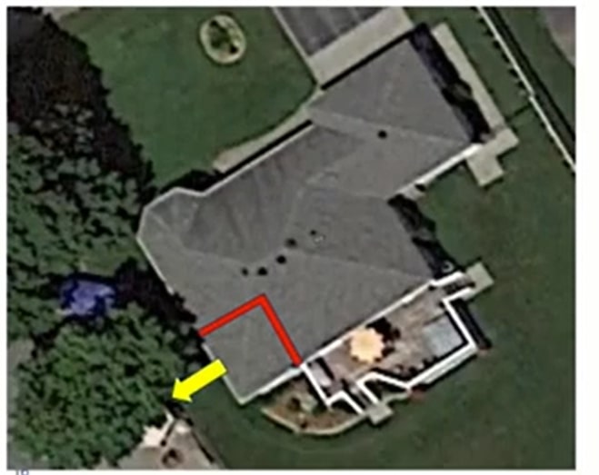
Figure 24: An aerial view of the home. Source – Google Maps
The red right angle in figure 24 shows the area of the damage. Underneath that marked area was the den, and it had a cathedral ceiling. In a typical room, two edges of the walls have ceiling joists running across the entire length of the room. To create the vaulted appearance of a cathedral ceiling, you have to remove the ceiling joists. In the absence of these joists, rafters must be adequately braced.

Figure 25: A picture of the framing of the home from 30 or 40 years ago.
The image above shows a wall separating the den and the kitchen. The red line marks the edge of the kitchen wall. At the top of the kitchen wall edge, there are 2′ by 6′ ceiling joists that are cut. The blue line represents the intention of the designer to extend those joists from the kitchen wall across the den to the exterior wall that ended up protruding and bowing outward under the snow load.
Had those joists been installed, they would have provided additional support for the exterior wall, pulling and securing it against the internal kitchen wall. It would have prevented the cathedral roof failure.
Preliminary findings and analysis
We were dealing with old construction from the 1990s, and its design records were not available. The town switched corporate identities over the years, and documents were lost. So there was no way to tell if the issue was related to design or quality.
This presented a problem because the plaintiff had the burden to prove a claim falls within coverage. And then the defendant insurer had the burden to prove the exclusion upon which it relied.
Preliminary findings and analysis: Case Law
In the case of Dawson Creek v. Zurich, the British Columbia Court of Appeal looked at very similar facts. The two cases had virtually identical facts. In the Dawson Creek v. Zurich case, an arena roof collapsed under snow load. The building was 40 years old, and there were no records of the original design.
The argument was that it must be a design or workmanship issue. If the builder fails to install the joists, it’s a quality issue. Suppose the joists were never supposed to be there by design. But the court didn’t accept that reason. So the insurer still had the onus to prove one of the exclusions. But the lack of records and facts made it impossible to prove any of the exclusions applied. So the insurer could not prove either exclusion.
There’s a similar case in 2008 from Ontario. In that case, the court said that Inherent Vice is challenging to define. Some courts have referred to it as deterioration of construction materials. So, you would need to have evidence of deterioration. But that wasn’t going to be likely on our set of facts because we’re dealing with a failed roof. So, we could not establish corruption.
In Dawson’s Creek v. Zurich, the Court of Appeal reasoned that you’d also have to prove that the defect was, in fact, latent. As part of this latent defect exclusion, you’d have to show that the fault was not discoverable upon inspection. They also said that it’s an exclusion that should be considered distinguishable from construction defects, excluded explicitly under the quality exclusion. The Court of Appeal went on to say that the Inherent Vice and Latent defect exclusion should generally apply more to perishable goods.
We knew we had to prove the faulty workmanship exclusion based on these two previous rulings. We acquired a copy of the blueprint for the home.

Figure 26: The blueprint of the home.
The yellow line on the blueprints represents the joists. It intends to connect that exterior wall to the wall that failed under the cathedral ceiling to provide additional support across the back end of the home.
To acquire the blueprint, we got a copy of the subdivision plan, after which we identified homes with similar models. Then, those homes were visited, and we found a blueprint identical to the design of the collapsed house.
Resolution
The blueprint helped us prove the quality issue because it clearly shows that the joist was supposed to be there and that the builder went against the design specifications. While this information was invaluable, the case wasn’t closed. We had to rely on the exclusion wording on the insurance policy. The Homeowner had an “all-risks” Homeowner’s policy, including specific collapse coverage.
Figure 27: The policy wording.
The Homeowner’s insurance policy had a resultant damage exception. As indicated in figure 27, the policy did not insure the cost of making good faulty workmanship unless physical damage not otherwise excluded by the policy resulted.
The plaintiff argued that their roof collapsed because lateral bracing between the rafters in the cathedral ceiling was not present, as shown in the exemplary photo below (figure 28):

Figure 28: The exemplary photo of the cathedral ceiling.
The dark wood rafters show that there are no ceiling joists. The plaintiff argued that a relatively inexpensive fix to the lateral bracing would have prevented the roof from collapsing. The insured’s position was that the engineering opinion lacked lateral bracing, allowing the rafters to shift in the same direction under a load of snow.
The same forces push the exterior walls outward, and the lack of lateral bracing could be remedied with inexpensive steel strapping. The point of this argument was that everything else was resultant damage. Additionally, we still needed to look further into the scope of the damages, and this is what we discovered:

Figure 29: A drawing showing the design and construction of the house.
The white line depicts the cathedral ceiling, and the orange line shows the joists that were supposed to be in place but were not. Upon further inspection of the damages to the roof, we noticed that the collar tie indicated by the blue was over-spinning. It was twice the length required by the building code.
The rafters that were supposed to be spaced out every few feet were spaced out twice the length of the building code requirement. We determined that the builder ultimately failed to install the roof to code or design. As a result, all rafters and collar ties had to be replaced. In addition, the joists had to be installed, and the cathedral ceiling had to be adequately braced.
Ultimately, the entire roof was excluded for faulty quality, while the main floor and basement were likely resultant damage.
Case Study 3: Concurrent coverage
A flood occurred at night, during off-hours. The resulting damage to a water line caused a leak. The water damage occurred while adding to a commercial building under construction. There was a Builder’s Risk insurance policy in place during construction. There was also First-Party property insurance in place for the existing building.
Waterline failure caused damage throughout the existing building. The concurrent coverage was the First-Party property for the system building and the Builder’s Risk (COC).

Figure 30: A photo of the waterline that failed.
Initial observations
In figure 30, you can see that the coupling engages a fair portion of the pipe that it’s attached to, leaving only a limited space for the other pipe to adhere. This could potentially be an installation issue. But on the other hand, there are odd cuts in the pipe, indicating a lack of care or a coupling issue.
The parties covered under the Builder’s Risk included the owner, general contractor, subcontractors, security staff, and suppliers. In addition, the owner is also covered under the First-Party property policy.
Preliminary findings and analysis
The failed water line was removed and stored for destructive testing. The representation at the testing was intended to include the anticipated insured individuals. The insurer’s investigators conducted interviews, including with the representatives of insured individuals.
Resolution
All those connected to the waterline were covered under the Builder’s Risk. Therefore, further investigation was determined unnecessary. As a result, destructive testing was never carried out, and the cause was never determined. However, a chain of custody and preservation of evidence issue arose nonetheless.
A cautionary note here is the lack of consideration for a potential manufacturing failure. The investigators did not consider a manufacturing warranty to respond to this loss. By removing the pipe and not ensuring a chain of custody. Even if there were some exposures on the manufacturer, there’s a potential for a limited liability clause in the warranty wording.
It is difficult to say whether this manufacturer would have ever been responsible and potentially unlikely, but it bears a cautionary note. The main issue that arose after this investigation was jurisdiction.
The two insurance companies did not know how to divide the loss. The debate over the jurisdiction cost delays and potentially caused prejudice to the insured. Those delays prevented the repair of the building from occurring promptly.
OCI Group: Leading Experts for Structural Claims
Our forensic experts have a lot of experience conducting investigations, writing reports, and testifying in court as expert witnesses. Call 1-888-624-3473 if you’re dealing with structural complex claims and property loss. We will conduct a comprehensive investigation based only on facts and evidence.